Digital Dj’ing has become too clean.
When I was an early adopter of M-Audio’s Torq there were no usable controllers at all (let’s not even think about the xponent, never saw such an ugly piece of plastic).
At first I used a Berhinger BCR together with Bome’s Midi Translator.
Later I built my own Controller specifically taylored for my workflow with Torq. Technically those solutions were far from being perfect, mainly caused my a lack of feedback possibilites of the software and by mechanical imperfections that occur when you build a controller without paying enough attention for the necessary precision.
Nowadays the situation has changed drastically. There’s a huge amount of great Midi controllers out on the market. You only have to plug them in and that’s it. Most of the DVS-packages even come with pre-configured tepmplates ready for you to start dj’ing without any worries.
I don’t like it.
I just can’t help myself but for me digital djing always includes the need and the passion for some amount of own development.
This surely can only be done in an area where errors can occur and you are not a stadium-filling super-paid person, but then … this isn’t djing…that’s a concert.
anyways.
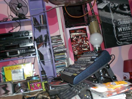
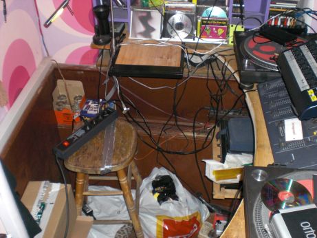
When I went out making music I normally took this with me.
(yes… a wooden board)
I really like playing around with timecode vinyls. Mixing is pure fun with these things. Unfortunately there is a rather high potential for errors and stepstones. A broken ground wire on a turntable, faulty contact fields for the needle, dirty electricity (when the hot water boiler is in the same circuit as the p.a. …). Furthermore Torq’s very own soundcard -the conectiv- is higly prone to errors because of voltage hickups….
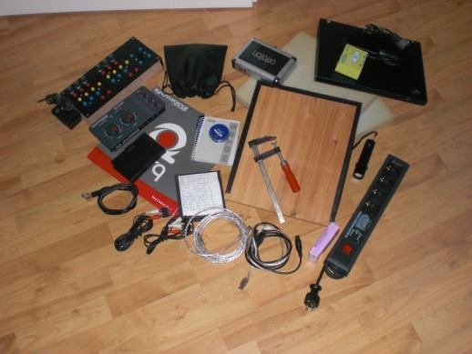
There’s absolutely no fun in carrying all this stuff around town just to realize you forgot one fr*ggin cable.
That’s why i tried to slim down my equipment as much as possible.
(Meanwhile I switched to Torq Version 2 and fortunately there are no limitations to using the conectiv (or any other torq hardware) as a dongle for copy protection so I could get rid of this easily.)
I don’t want to stop mixing and beatmatching myself (not using auto-sync or other helpers) but scratching and cutting in most cases is nothing for the places I play music. That’s why I still need some sort of jogwheels but can happily get rid of timecode vinyls.
I could have bought anything like the vci-380 or any common controller with usable jogwheels but even that is too much for me to carry. Leave alone the missing space behind a small bar’s dj ‘booth’.
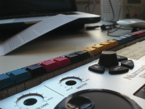
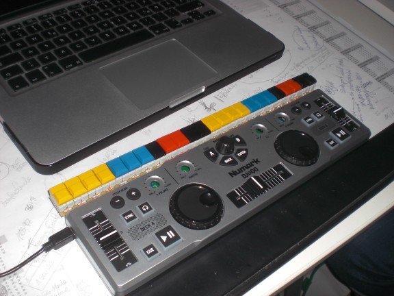
I came across the Numark dj2go a while ago and gave it a try. And even though it takes some trial-and error the Jogwheels can somehow be used for ‘platter emulation’ (don’t expect too much). Interestingly there are ~zero videos around where the jogdials of the controller are used. Maybe noone really took the time…
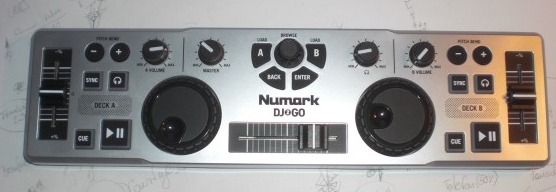
Only backdraw of this solution is the fact that the controller is missing a few buttons for the workflow I developed. I’d like to have some buttons to jump to cuepoints, set (and release) loops and maybe trigger a few effects.
On the other hand side the controller has some things I never use since I’m using an external mixer: Channel volume A and B, master- and headphone volume on a midi controller are just unnecessary for me. That’s why I sacrificed them for some buttons.
So, here we go.
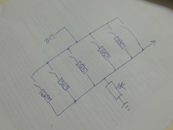
The 4 potentiometers on the top half will be exchanged for buttons. This way there are no continous messages of the corresponding CCs any more. Instead every press of a new button will create a somewhat unique CC-vlaue ‘click’ (more on that later). This is done by some simple ladder of resistors. The resistors’ sizes are calculated to fit different needs:
I wanted this to be as simple to rebuild as possible. One resistor for every button should be easy enough.
Furthermore these are the most common resistor values. No problem on getting these anywhere. I also wanted to be on the safe side and select the resistors in a way that the corresponding voltage drops (the midi outputs) are as far away from eacht other as possible. That way the circuit will even work -at least some kind of- stable in rough surroundings (very hot/ cold temperatures that make every resistor change its value to a certain degree).
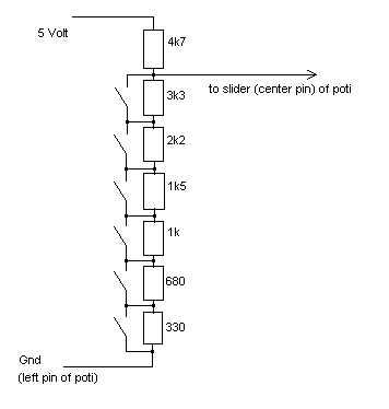
(All resistors are 5% tolerance.)
The resistors form a simple voltage divider. The supply voltage is 5v. Since everything in the controller is handled with 3.3v the values of the resistors make sure the output voltage never goes above 3.3v (see below).
There is one major disadvantage, however: Simultaneous button-presses will not be able to be realized due to the nature of the construction. Keep this in mind when slaughterig your controller for this.
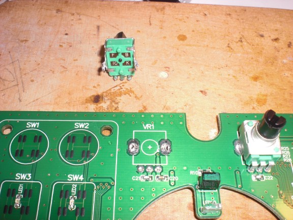
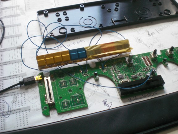
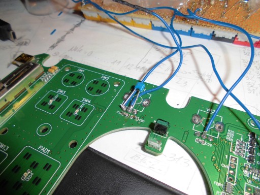
First up, the case needs to be opened and the poties have to be removed. Avanti warranty! Interestingly, I don’t feel any kind of shiver any more when doing things like this. Voiding the warranty and taking the risk of destroying a basically new and unused controller I just bought seems to be the most normal thing in life. Good. It took me long enough for this =)
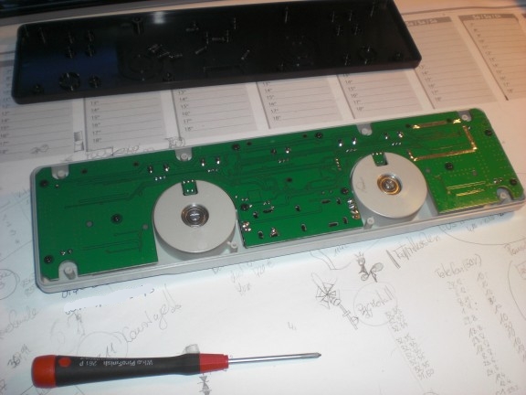
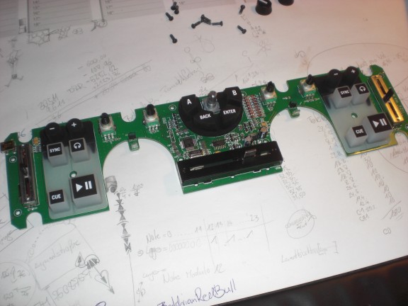
The SMD capacitors below the poties don’t have to be removed. I tested the results with the parts being removed and it’s better to keep them soldered. Never soldered SMD before but I got the two caps back in place at 1 o’clock in the night with 2 big glasses of beer in my …headstomach. Seems normal.
Otherwise: If it didn’t want to be treated that a way it shouldn’t have become a Midi-controller. Damnit.
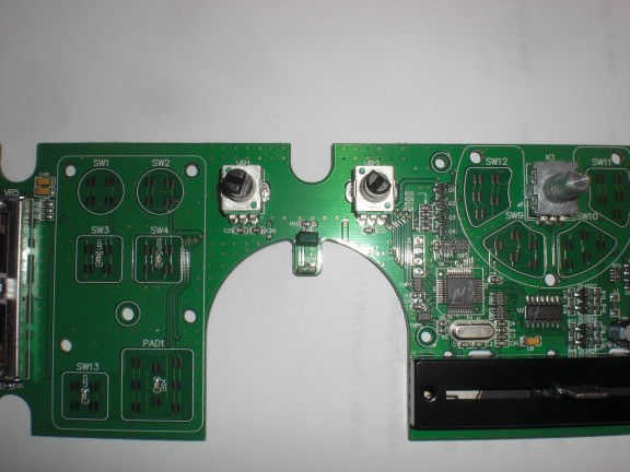
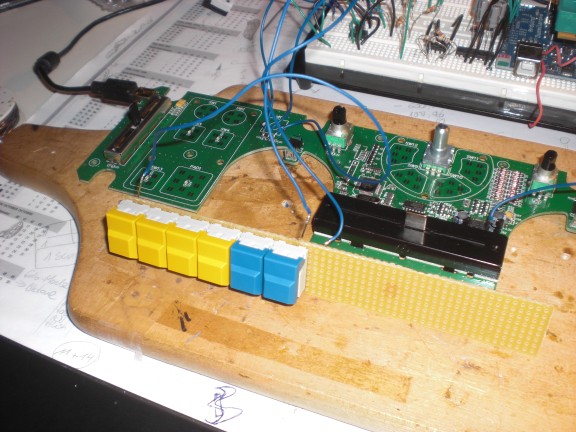
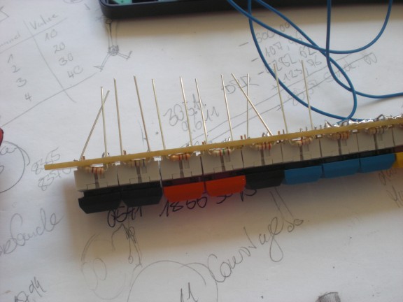
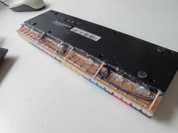
Next the buttons are soldered together. Every potentiometer is exchanged for six buttons. 2 Groups of buttons (12, that is) are fitted onto one stripe of vectorboard. That makes 24 new buttons overall which not only is a somewhat insanely high amount of buttons but which also is the maximum number of buttons that can physically be fitted on top of the controller.
Every button has one pair of contacts which opens and one which closes upon buttonpress. Make sure to get the correct one (the one which closes).
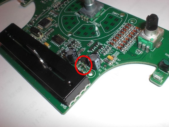
One thing I found out is that the controller uses 3.3 volt internally. To make the voltage drops on the resistors as big as possible I took 5 volts as a supply logic for the buttons. Stole it from a little pin I soldered to the board. The spot is easy to find since it’s situated next to the 3.3v voltage regulator. And because it’s labeled.
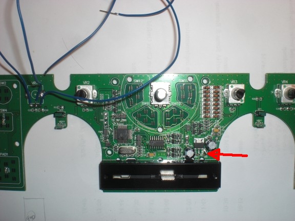
As mentioned before the resistorvalues make sure that the maximum output voltage never exceeds 3.3v.
Btw: did you realize the light barriers? This might be the cheapest possible solution ever to easily get some feedback from the jogwheels… should keep this trick in mind for later use.
The case needs a little dremel action for the cables to connect.
And everything needs….hotglue! yeee-haw!
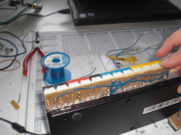
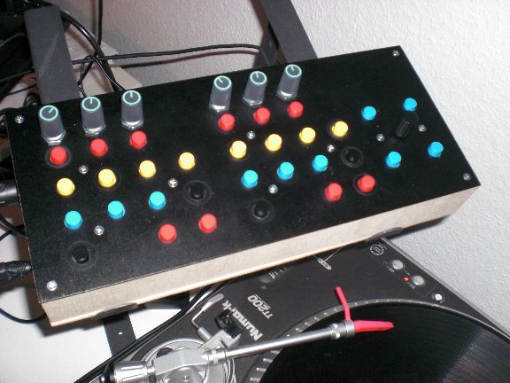
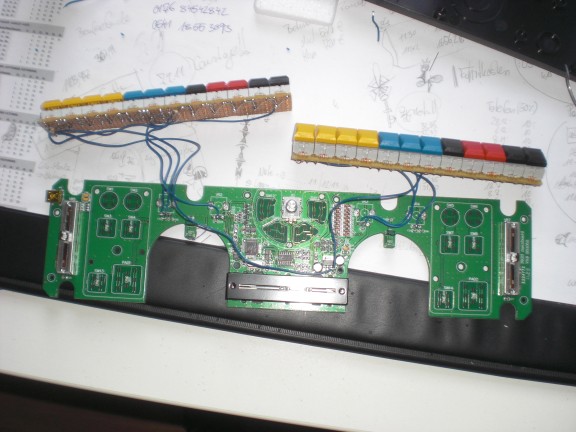
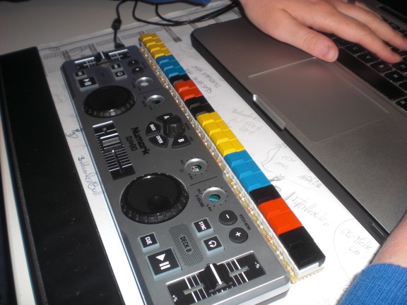
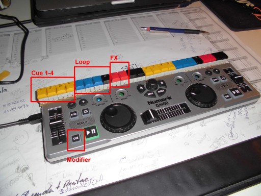
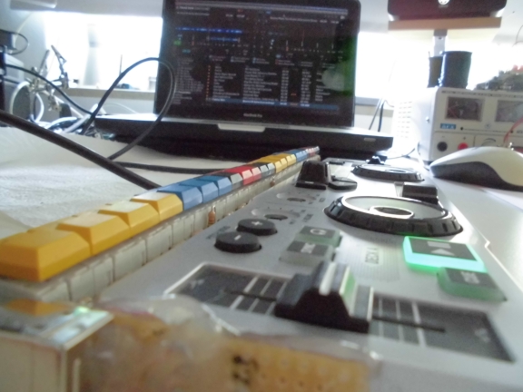
And here we go: 24 shiny new buttons attached to the Numark DJ2GO:
That was the hardware part. Now we have to take care the buttons send useable MIDI-values.
When the original potentiometers were attached every poti sent a continuous stream of CC-values when it was twisted. Now that we exchanged them for buttons we still get CC values when the buttons are pressed. They are, however, not continous any more but somewhat stepped.
There are three problems with this. First up, most DVS systems can’t handle the same Midi-CC for different software-commands. When you map the first button to “cue 1” it will map “CC #8” to it. The difference of the CC value between button 1 and 2 isn’t recognized. That’s why we have to convert different values of the same CC to different MIDI Notes.
Second problem: The buttons are bouncy as hell. Even though I bought the extra-expensive ones to NOT face this problem they create quite some nasty bouncing when pressed and released.
Third problem: the controller’s internal logic seems to do some even-out-processing in this area. This makes sense when poties are attached but isn’t very helpful when we have buttons. Even when the controller gets some perfect bounce-free signal the controller spits out something between 2 and 6(!) CC values.
Problem 2 and 3 make it we have to do some external software debouncing.
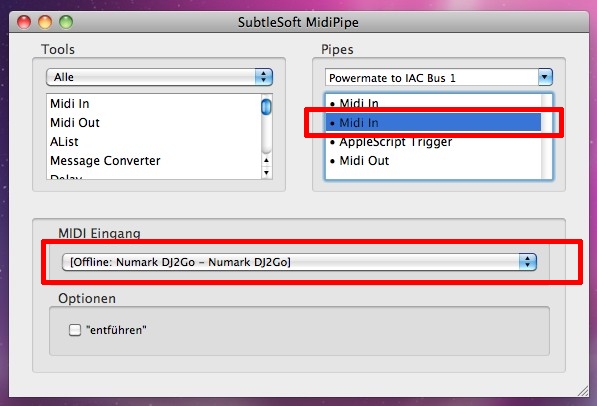
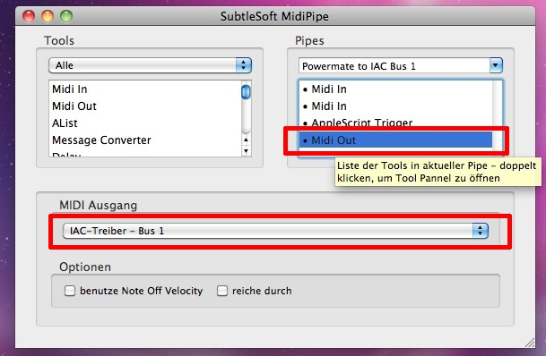
Using a Macbook I found Midipipe to be the best tool for the job and wrote a little script for it.
In short: CC values coming from the controller are sent to Midipipe where they are temporarily stored.
In order to debounce (and in order to come across Applescript’s limitation of being single-threaded) a second script is triggered. This script does nothing more than to wait ~40ms and tell Midipipe to continue by sending it a certain MIDI message back via a dedicated port.
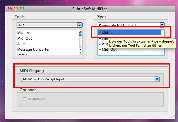
The CC values which came within the last 40ms are then transformed into individual MIDI Notes and sent out via the IAC MIDI port into the software.
Both scripts are a little buggy still and need some fixing.They will be made available soon. Contact me if you urgently need them.
The whole system is far away from being perfect. Sometimes the buttons don’t become recognized … but … that’s great – somehow. Adds some flavour. At least everyone will otice I’m not using auto-sync when things are messed up.
I love this.
[17.11.2012]
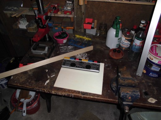
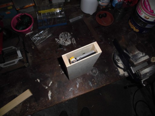
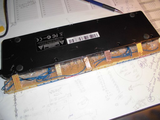
There has been some progress, lately. First up when I visited my parents I used my father’s toolshed to build some case out of plywood in order to be able to transport the controller without breaking it:
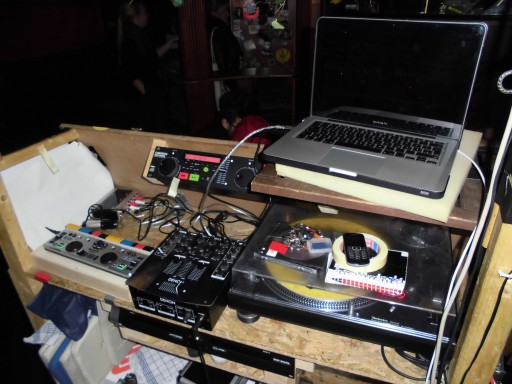
Secondly, I was out making music with it for the first time outside my home. This took place at the Freundlich & Kompetent in Hamburg.
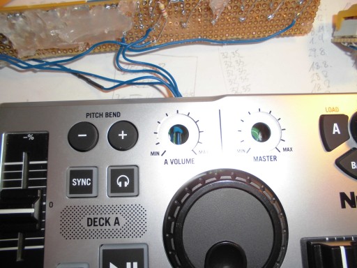
And as expected the controller failed BIG TIME. Somehow there was lots of electrical shizzle around and the modified Numark controller seemed to catch it all. Showing this in the loop section for ‘Deck A’ behaving totally random without even touching the device or any of the cables around.
Well, I deactivated this function in the Midi-Editor and went without it that night. Not a big problem (The night was great, by the way…The bar has a super nice crew).
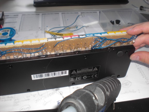
Back home I did some deeper investigation and after applying an insane amount of hotglue I realized that my midnight soldering skills (after some beer…see above) seem to have left me. One of the wires connecting the buttons to the contacts of the former poties was quite sensitive to impact. Midi data were created upon … breathing onto it… I guess that relates to one of the SMD caps I temporarilly desoldered for testing purposes got killed.
So … after a heavy research I made an educated guess and then took the first thing that came into line of sight and added an extra capacitor (47 nf for those who care) and … everything seems to be perfect now.
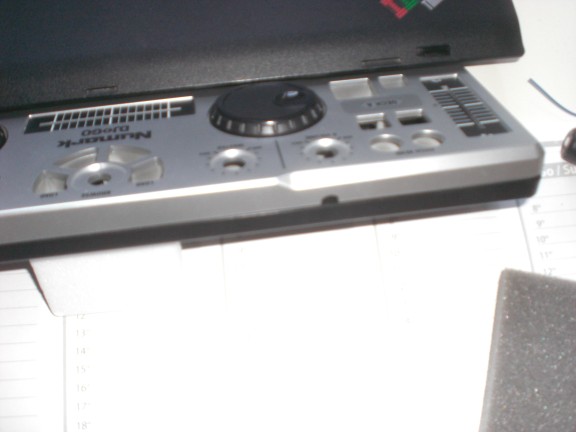
You can even see it after the enclosure has been put back together =)
The buttons are now a little more sturdy as well due to an improved construction of leftovers from various vectorboards. Everything is hot-glued, of course =)
Anyways, this is the current configuration I use (same for ‘Deck B’). I will post a video of this together with the current version of the Midipipe-script soon.
[tube]https://www.youtube.com/watch?v=RHNpYeziWV4[/tube]
[4.9.2013]
Oh man ….
to make things short: even after adding a new capacitor I experienced a faulty behaviour from time to time. This resulted in ‘phantom button presses’ (a loop or a que was triggered without touching the device) preferrably in situations when it was very hot and/or humid around. Looking at the circuit diagram above it becomes clear why: The circuit was always closed in some way. Current was flowing the hole time. Everything that might have caused even little changes in the resistors’ values (temperature being one of these things) MUST have caused a changed current and therefore some ‘phantom’ action.
Looking back that seemed to be the perfect circuit to provoke such a behaviour. Might keep this in mind for later use …
As soon as I realized that i built an … improvable … thing it became clear to me that I had to change the circuit. The new circuit now only causes current to flow when any of the buttons are actually pressed and furthermore widens the range of values that are created when a button is pressed. That way I could change the midipipe script to use a wider hysteresis to make operation even more reliable:
Putting it all back together I found a new way of fixing the buttons to the controller. I used scrap parts of vector board for this before but toothpicks do a much better job in my eyes
Looking as good as new from the store
[Update 10.11.2013]
The controller works like a charm now. There are only little things left to improve. One of the things is to make sure I’m not pressing the wrong button when using it without watching. So I added this little piece of plastic. (the one between the black and yellow buttons.) Doesn’t sound too impressive but it really helps preventing wrong button presses since my fingers ‘know’ where they are.