[This post has been updated a few days after it’s initial release: All the files are made available and various pieces of information have been added]
This project has been sponsored by PCBWay. Read below for more details on this.
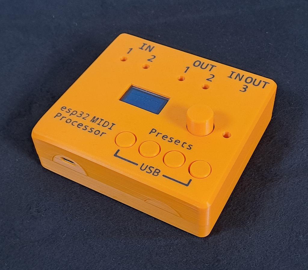
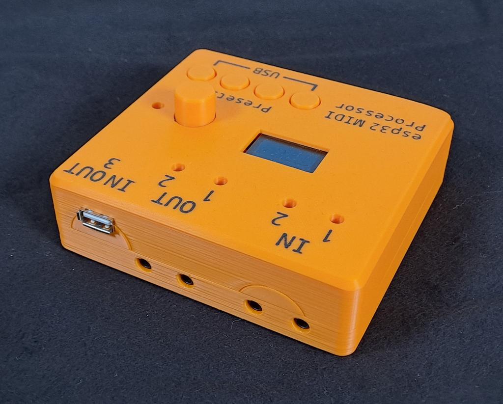
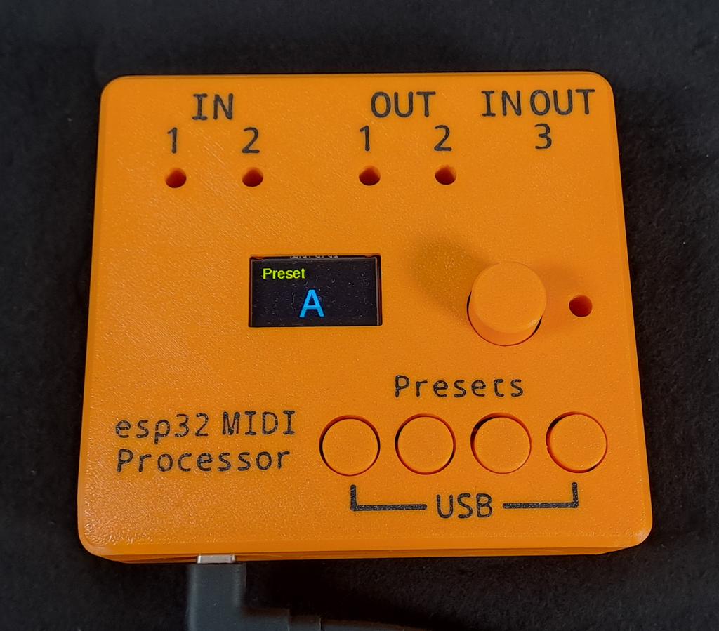
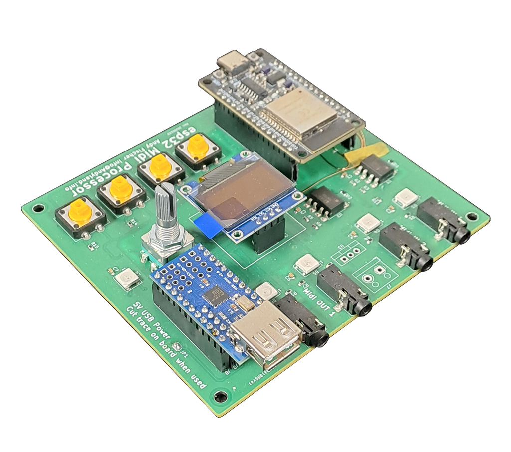
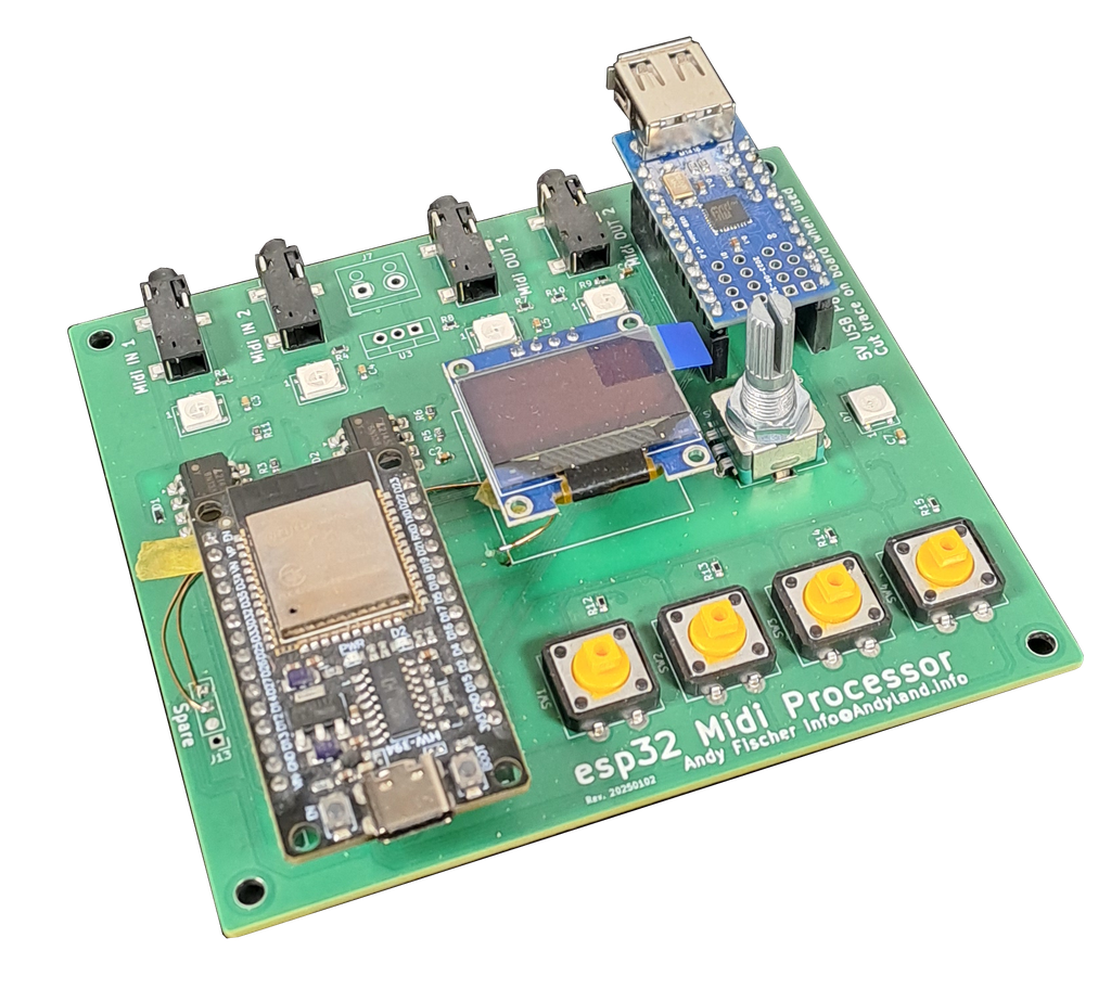
While developing the ClockBox I had some ideas that were not suited to be put into that project. However, they were too good to be gutted — at least for me. That’s why I developed the esp32 midi processor. In short: it’s an esp32 with 2 independent Midi IN- and 2 independent Midi OUTputs, a USB-host adapter and some buttons, etc. The circuit itself might also serve as a base for the next years of midi projects to come.
The first thing I built with this platform is a universal midi processor/modulator/merger.
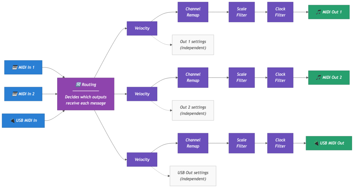
Incoming MIDI data (notes, CCs, MIDI Clock) can be routed and modulated. Every output can be modulated independently. As of firmware version 0.98 these are the available features per output:
- Route every input to every output
- Merge MIDI data per output
- Modulate velocity:
- velocity passthru (no modulation)
- set to 63
- set to 100
- set to 127
- randomize
- randomize around 100 (95..105)
- Modulate a note’s MIDI channel:
- passthru
- set channel to 1..16
- Modulate a CC’s MIDI channel:
- passthru
- set channel to 1..16
- Scale filter: only allow notes that fit to a given scale to be processed:
- passthru (off)
- major
- minor
- pentatonic major
- pentatonic minor
- Filter/block:
- passthru
- block MIDI clock
- allow only MIDI clock to be processed
I had AI create somewhat of a flow diagram to give an easy-to-grasp overview. Lessons learned: It looks 1000x more serious when a corporate-style diagram is present.
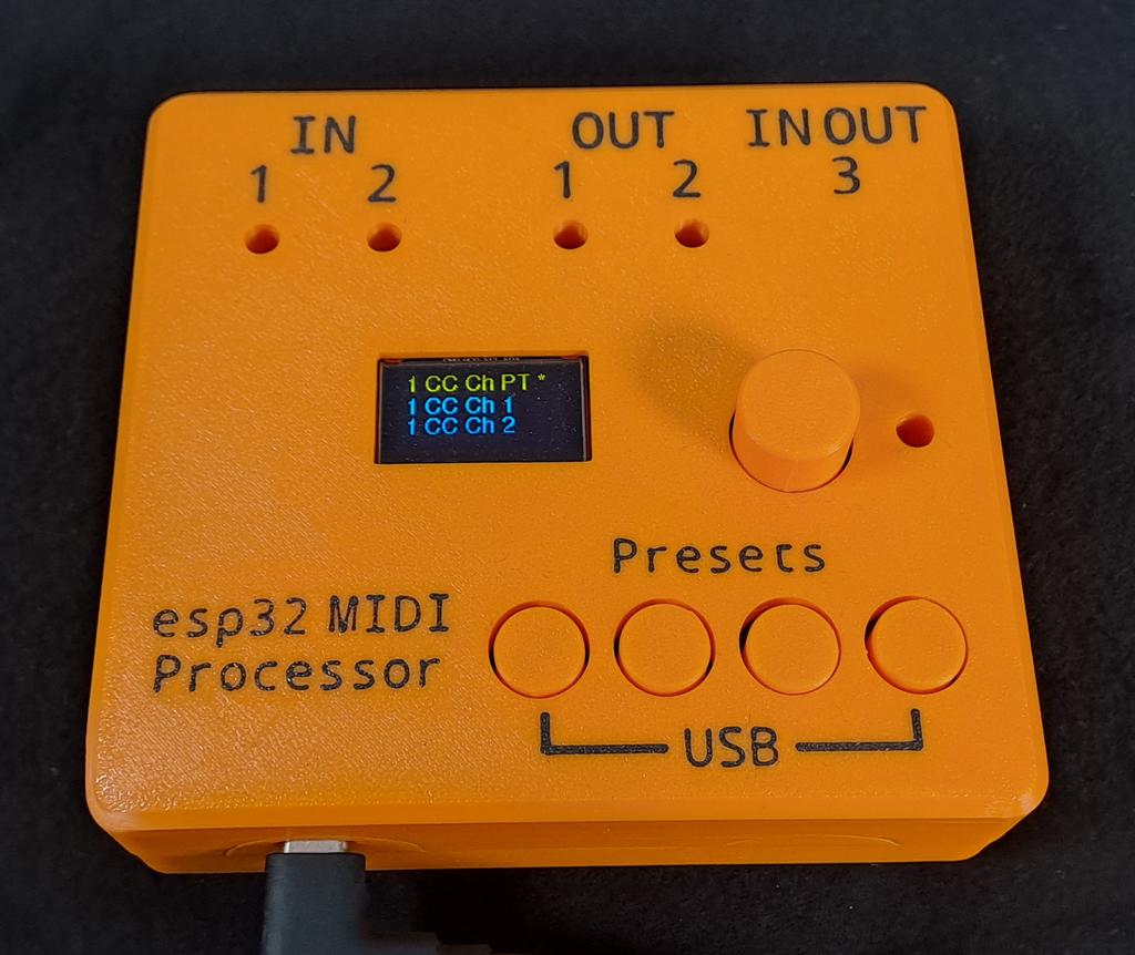
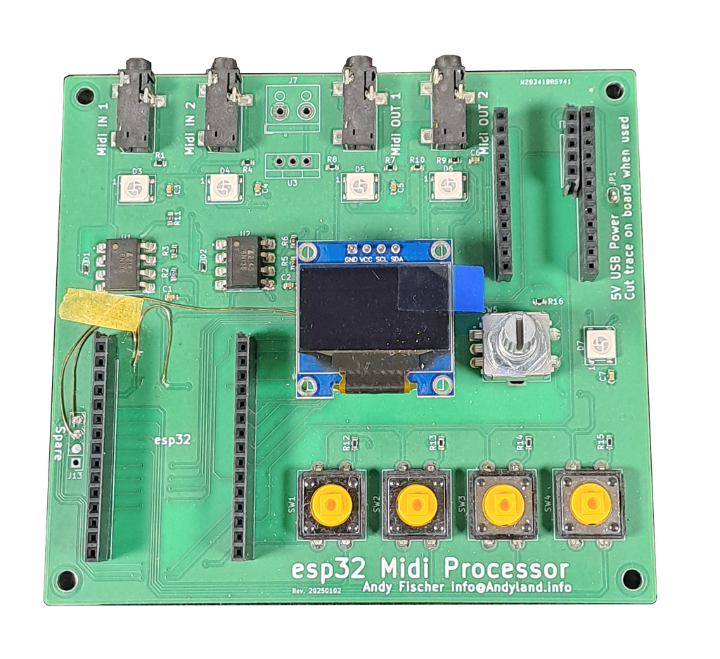
Modulators are set by using the rotary encoder next to the display: Simply twist it until the desired modulator appears in the top (yellow) line of the display and press down on the encoder. This will activate the selected modulator. Active modulators are indicated by an asterisk next to them. The picture below shows the modulator for CC channels on output 1 being set to passthru (PT). This is also the default setting: CCs are sent out with their respective channel values unchanged.
The fact that the modulators are applied to the outputs independently allows for a maximum of possible combinations. For example: You can use a midi-keyboard on input 3 (USB) and route the midi data to output 1 and 2 (TRS). Output 1 is connected to a synth which runs on channel 3, output 2 is connected to a synth that runs on midi channel 8 and needs a fixed velocity and reacts allergic to incoming midi clock data. Sounds like a plan to me =)
Since it’s over 200 attributes that can be set I also implemented a handy preset function to keep everything usable: Every configuration can be saved and recalled as one of four available presets. Pressing and holding a button for 3 seconds saves the current configuration into a preset, simply clicking a button recalls the saved settings immediately. The firmware is mostly handcrafted. I developed major parts ~2 years ago and only did the last things with help of our new AI overlord. Everything is available on Github.
As mentioned in the beginning, this project has been sponsored by PCBWay. For me this is a win-win: I would have used their services anyway since my experience with them on previous projects has simply been awesome. Them approaching me offering a collaboration on a project of my choice is one of the cooler things to happen to me. For other people (youtubers, streamers, influencers, etc) this is probably not a big deal but I am just here doing my stuff, hot-glueing things together and trying to make it available for others to enjoy.
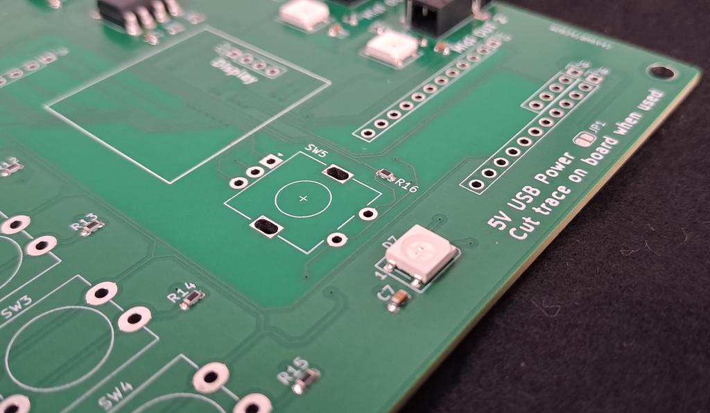
The fact that I received a set of 5 nearly perfect PCBs is by no means achieved by me or my skills. I messed up a lot of things when designing the circuit board: multiple incorrect BOMs, silkscreening on incorrect layer, footprints messed up — you name it. However, the folks at PCBWay found all my hiccups before going to production and offered a solution for every single issue. Most things got solved within one e-mail. That’s simply awesome. If you need any kind of PCB manufacturing I definitely recommend PCBWay for you to check out yourself.
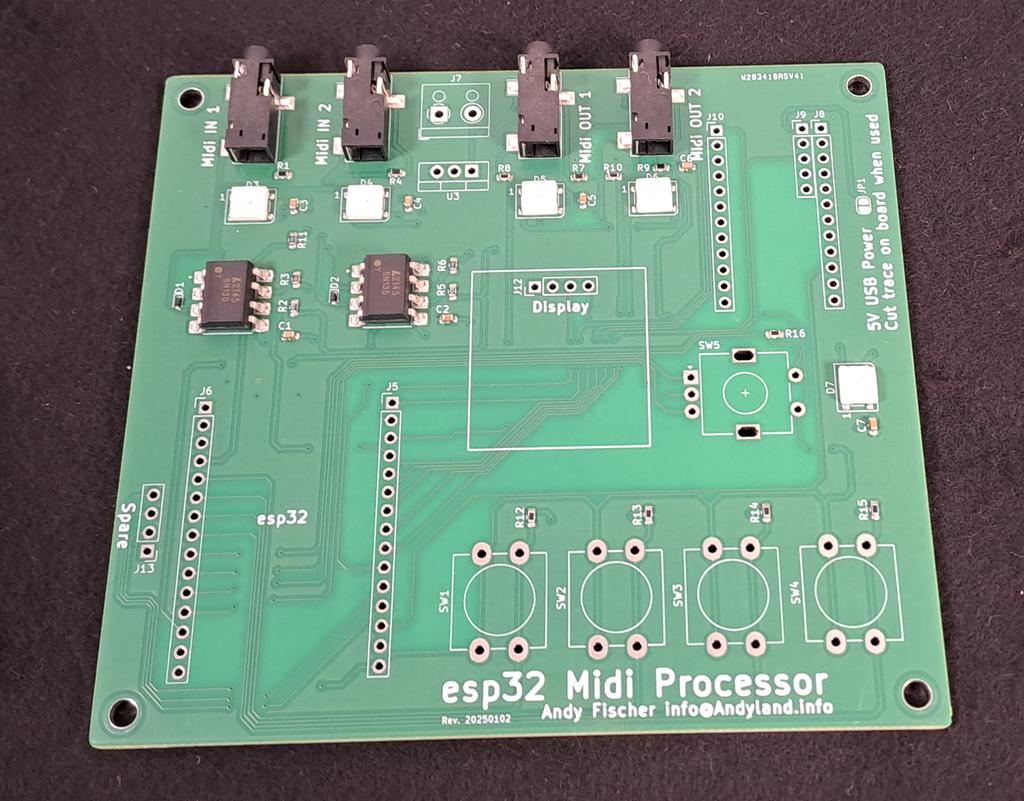
The boards themselves are just as good as you can imagine. Better still: On a previous project I had an issue with bad solder-joints on the TRS connectors (used the same ones back then) which I was reimbursed for back then. This time the connections are just completely flawless, which indicates to me that the people at PCBWay did not just tell me that they will finetune their processes for the next time but also really did it. That’s just cool. Here are a few details of the PCBs:
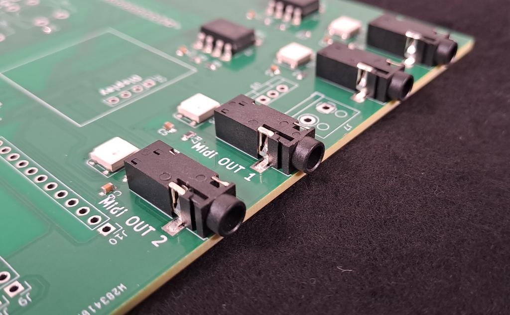
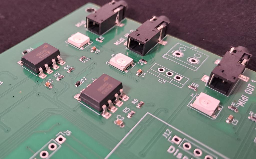
I designed the board to be a mix of SMD and THT parts: The THT parts being the ones that can easily be sourced via external providers and soldered without any special equipment. The USB-Host shield, for example, can be bought at various chinese marketplaces for ~2€ as time of this writing. It wouldn’t have made sense to have the circuit replicated myself. Same goes for the esp32 which serves as the brain of the device: I, in theory, could have created the complete esp32 with SMD parts so it would already be part of the finished PCB. But this is a hobby project. There’s kids running around and a house to maintain =).
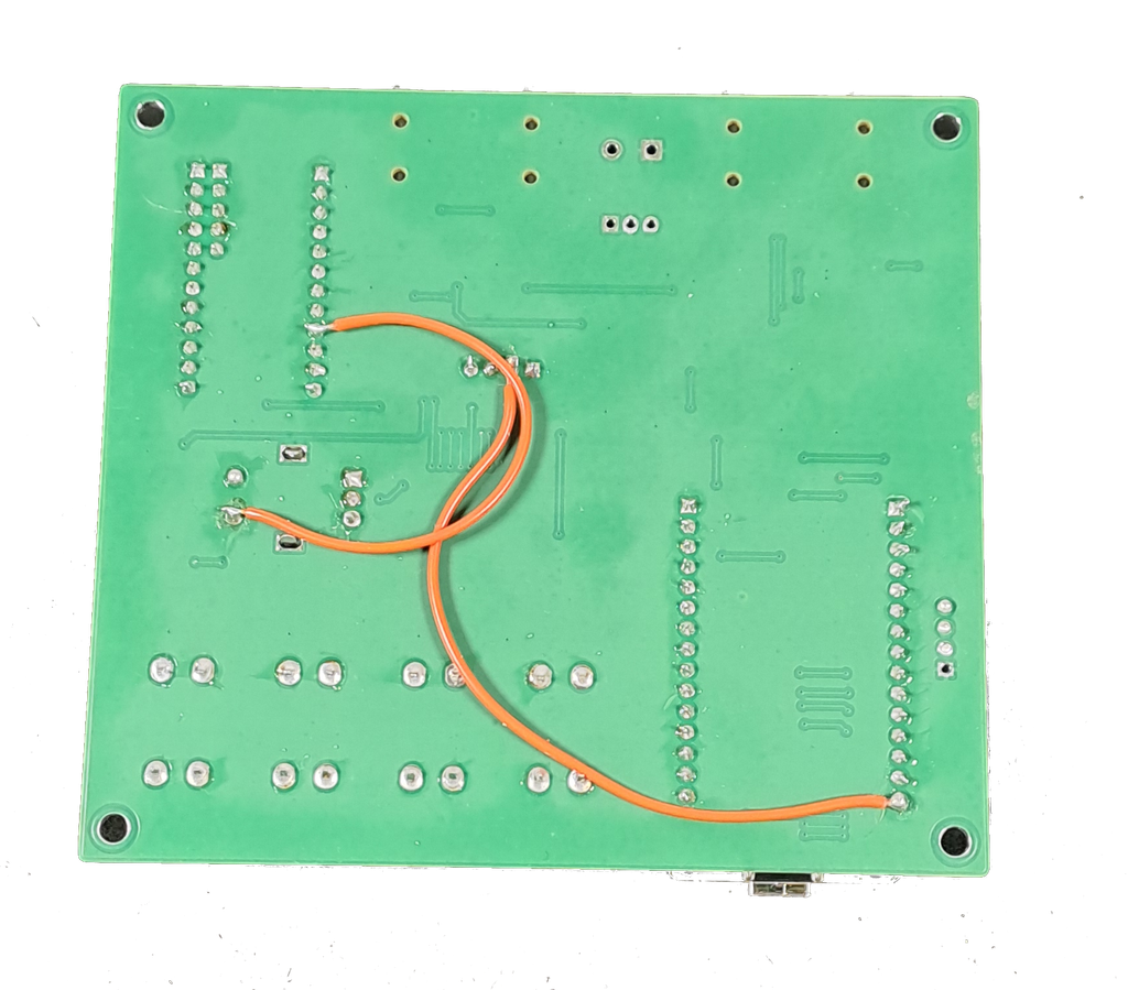
However, me being me I still managed to mess up a few things. I used some pins of the esp32 incorrectly and had to rewire a few traces. Normally, I completely build projects like these on a breadboard first, scribbling a schematic in parallel, turning it into a file in KiCad afterwards. This time I skipped some parts and trusted various documentations of questionable sources. Turned out to not be the best idea. Anyways, the fixes are manageable and require little more than a steady hand and a soldering iron. The latest version of the Github repository already contains the corrected version of the PCB.
Click the button to be directly handed over to PCBWay’s shared projects community and use this to order your own set of PCBs for this project

There’s basically zero risk of placing an incorrect order. The customer support is awesome and if anything is missing or your files do not make sense or your order looks strange you will be contacted by a real human being.
To complete the project you need the following components:
USB host shield 2.0: Amazon or Ali Express
esp32 Wroom: Amazon or Ali Express
i2c display 128×64: Amazon or Ali Express
temporary buttons: Amazon
rotary encoder: Amazon or Ali Express
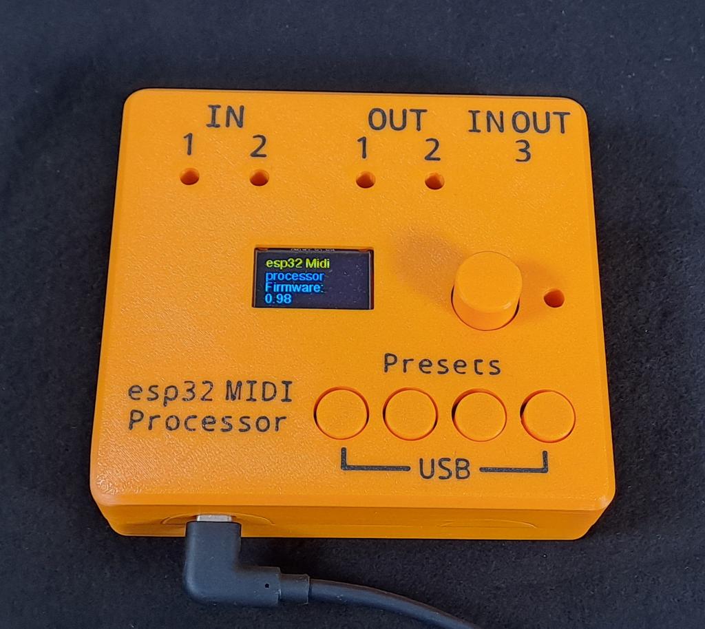
The casing was 3D printed and basically went “first try”:
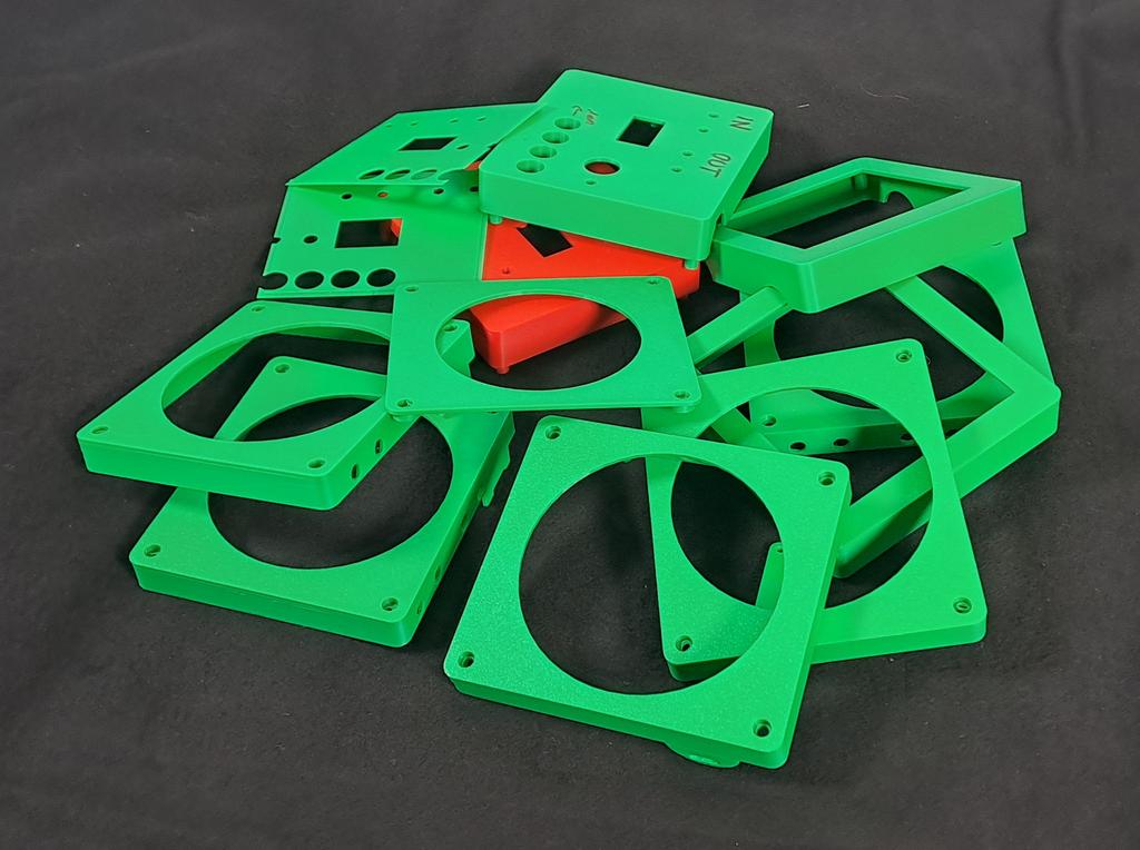
The end result works like a charm. I already have the next thing in mind that I will realize with this hardware.
All files are available over at Github. I also added the kicad files for the PCB as well as the revised bill of material for this project so you can recreate it yourself.