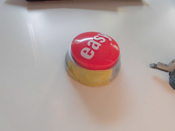
I guess everybody knows the Staples Easy Button.
[tube]https://www.youtube.com/watch?v=lkaAFObuUrA[/tube]
There are numerous hacks out in the wild adding some weird functionality to it. For quite some time I wanted to something similar. This is the documentation of how to make the Easy-Button a MIDI-USB device based on Atmega328 (Arduino).
Many hacks have in common that they are either relatively expensive (like…involving something with a dedicated teensy device) or rather ugly (due to holes just being sawed into the Easy Button’s case).
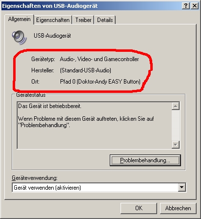
My first goal was to build a device that automatically identifies itself as an HID-compliant USB-MIDI device and gives simple MIDI functionality by using an Atmega328 and V-USB. In order to achieve a correct enumeration and to get a useful starting point I used the demo-versionof USBLyzer to get the necessary data from my KORG nanoKey and altered them in various places (Vendor ID etc..). (You will remember this one later.)
When the button is pressed a ‘MIDI Note ON’ signal is sent. Upon release it sends a ‘Note OFF’ message.
The second goal was to give it a clean overall look.
Let’s see…
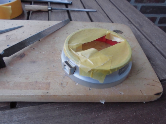
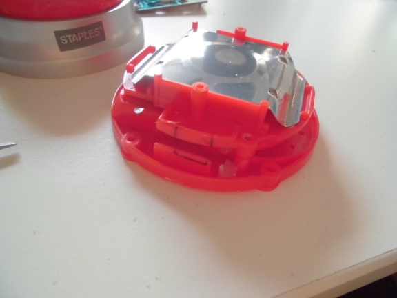
This is the Staples Easy Button with the cap and the clicker already being removed (which makes it just a pretty unidentifiable bunch of electronics and some plastic)
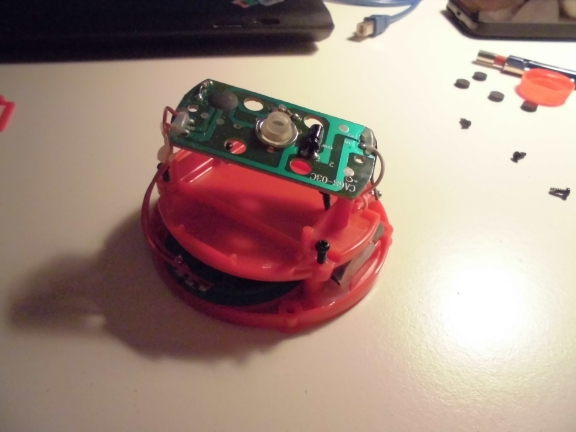
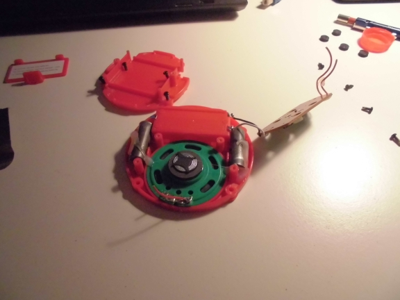
we don’t need the speaker so it will be gone soon….
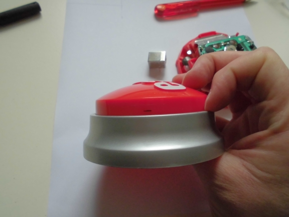
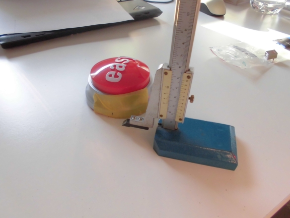
The black line shows how deep the cap goes when it’s pressed.
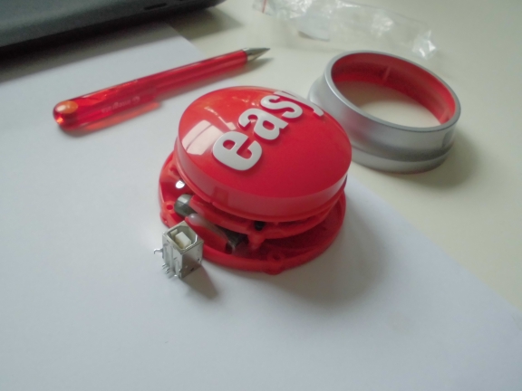
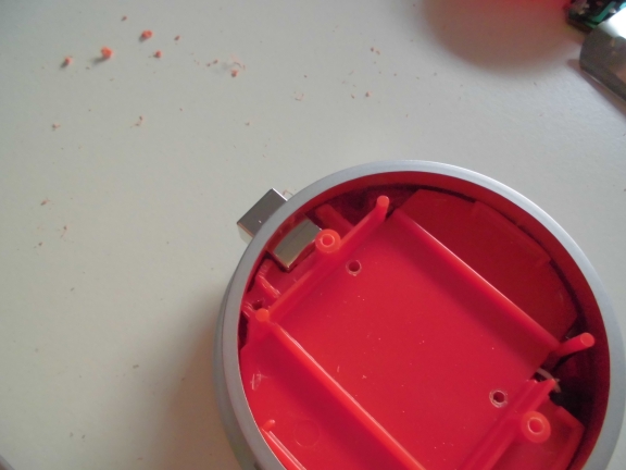
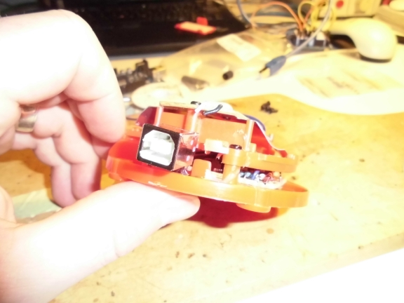
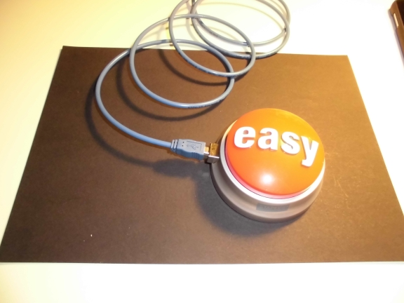
This is the spot where the USB connector will be placed
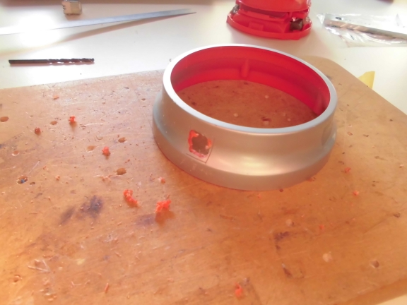
I might not be the best craftsman around (already mentioned that once before) but after some filing this one looks pretty decent:
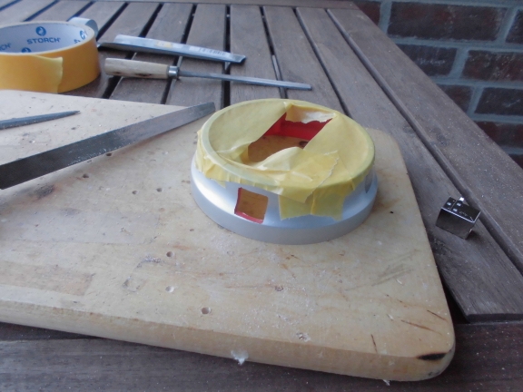
The plastic on the inside has to be cut as well
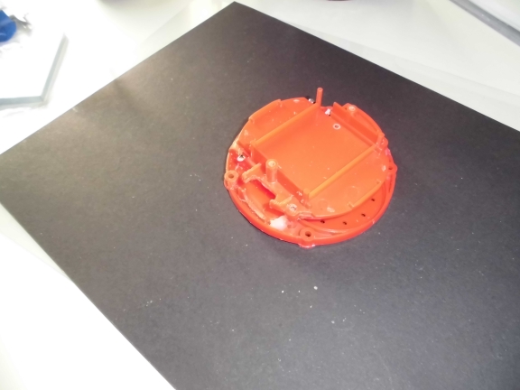
This DOES look quite well
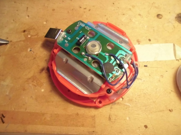
Now I need to add the circuit board. Due to the speaker being thrown out there is lots of space for that now.
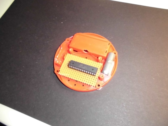
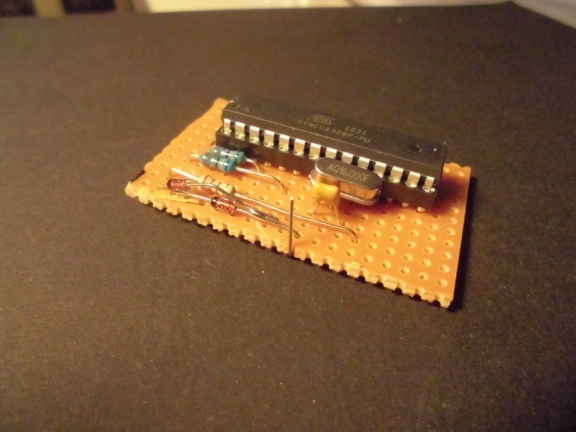
The circuit is basically a 1:1 copy of the V-USB keyboard example. The Button is connected with data pin 6 of the Atmega. It involves some creative soldering of the diodes because I didn’t care too much about the circuit’s layout before I started soldering.
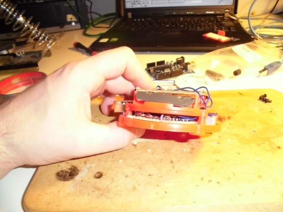
Everything’s coming to an end soon
It seems impossible for my camera to do any decent shots that contain the color red.
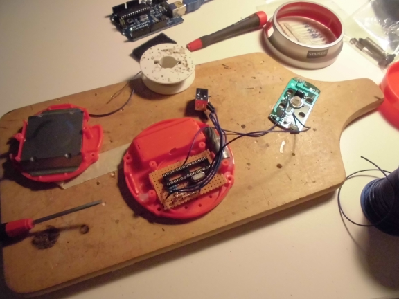
Anyway, you might get an idea of how the circuit fits into the structure.
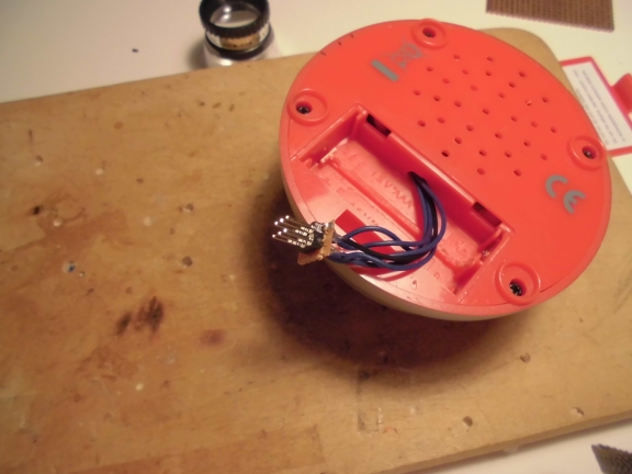
Some detail of how the actual button-mechanism is connected to the Atmega (the blue wires, you guessed it)
To make future additions a little easier I added an ICSP connector which fits nicely into what has formerly been the battery case
Finally… in all its glory.
I had this in the back of my mind for ~2.5 years now. Shortly before starting with this built I started wandering whether this might make sense or be worth the money or time invested or…..
F*CK IT. Never let doubts get in the way of your creativity. If this wouldn’t make sense than I probably wouldn’t have built it. Word! =)
The whole Arduino project (I did that arduino IDE 1.0.3) can be downloaded here. Unzip and copy the folder ‘Nanokey’ to the libraries-folder of your arduino IDE. Feel free to contact me if anything is left unclear.