Latest Insta
Or: Creating an audio-signal with an Arduino, feeding it into a mixing desk, altering the frequencies via the mixer’s eq and analyzing the processed audio with another Arduino which then turns it into a MIDI-signal. Yes, that is Digital-to-Analog-to-Digital-to-Analog-to-Digital-conversion. Phew!
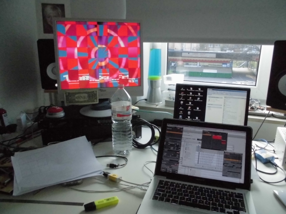
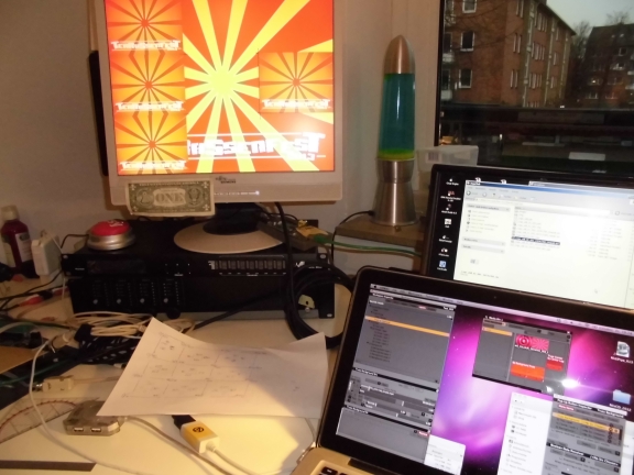
Here’s a picture of the setup:
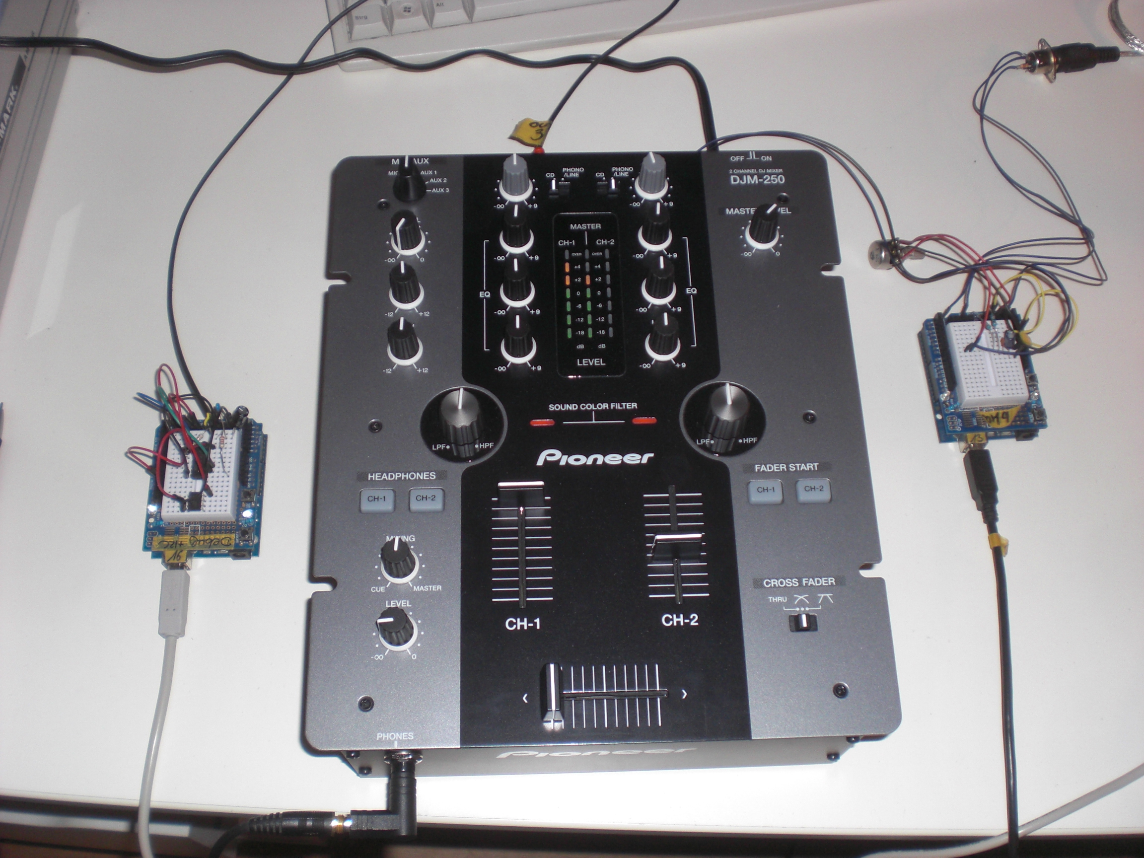
On the left side there is a circuit consisting of an Arduino and an Attiny85. The Arduino creates a low-frequency ( ‘bass’ ) sine-shaped tone which perfectly sits in the frequency range of the mixer’s bass-EQ. I did some testing here to find the perfect frequency. Testing means: Using Ableton Live to create a white noise, feed this into the mixer, feed the mixer’s output back into Ableton and use the Spectrum-tool to see which frequency gets most influenced by the bass-EQ (C2, that is).
Creating a somewhat true sine needs some effort since the Arduino’s analog outputs only do PWM which isn’t very useful when talking about low-frequency audio signals. PWM basically creates a square-wave signal with a certain pulse-pause relation. While this might be okay for dimming an LED, this becomes quite unusable when dealing with audio because you can simply hear that it’s no sine – the lower the frequency the more the signal turns into some sort of ‘click’-noise. No wonder, the bass-EQ doesn’t influence this to any convience.
That’s why I used this solution to make the Arduino spit out something that’s a little more sinewave-like. I ommitted the circuit as you may see on the picture below. I didn’t have the necessary parts lying around and it worked nevertheless.
The Attiny85 is used to create the second tone. It’s a simple PWM signal at 480 Hz. This time the PWM-nature of the signal can be used for our benefits: A square-wave signal has a recognizable amount of harmonics. You don’t hear one but (at least) two tones. Perfect for us because the mixer I used perfectly influences (well … “perfectly” ) the signals with its mid- and hi-EQs.
The code for the Attiny85 looks like this:
void setup(){
pinMode(3, OUTPUT);
}
void loop(){
buzz(3,480,100);
}
void buzz(int targetPin, long frequency, long length) {
long delayValue = 1000000/frequency/2; // calculate the delay value between transitions
long numCycles = frequency * length/ 1000; // calculate the number of cycles for proper timing
for (long i=0; i < numCycles; i++){ // for the calculated length of time…
digitalWrite(targetPin,HIGH); // write the buzzer pin high to push out the diaphram
delayMicroseconds(delayValue); // wait for the calculated delay value
digitalWrite(targetPin,LOW); // write the buzzer pin low to pull back the diaphram
delayMicroseconds(delayValue); // wait again or the calculated delay value
}
}
I guess I found it over here and adapted it to my needs.
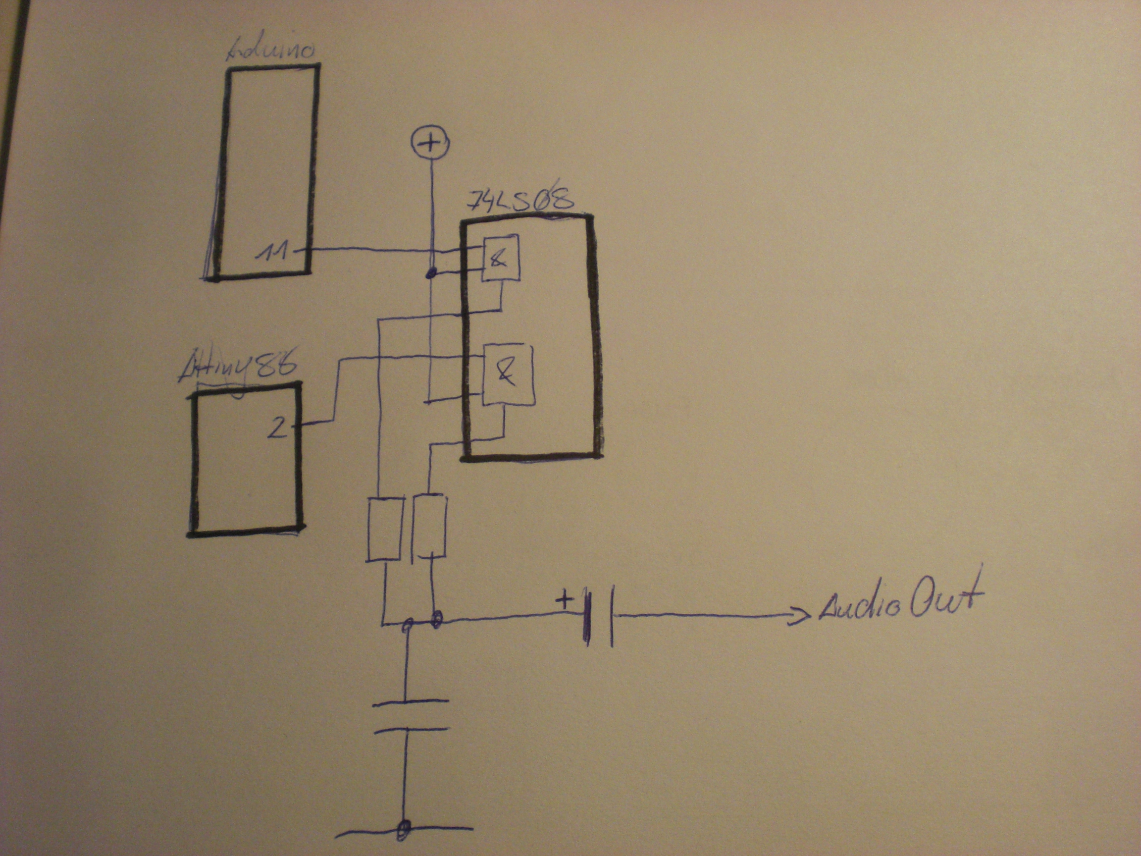
the two microcontroller’s output signals are fed into a 7408 (Quad AND) and then sent out into the analog world by a circuit I found over at the MunichMakerLab. This is my first audio-circuit with an Arduino. it’s probably spine-crawling for those who do this on a more professional base but I was getting the best results with this circuit.
[Edit] As someone pointed out in the comments section for this post on Hackaday this might read like I didn’t know at all what I am doing here or that it’s all just a big coincidence. This is not correct. The AND gate protects the audio sources from interfering with each other for a certain amount. I tested that, it simply sounds cleaner. At least I had a certain intention when I added the gates to the circuit (…not that I completely remember….). Looking at the circuit I am still wandering about _why_ but that’s one of the things that I file as ‘Audio things’ for now. [/Edit]
The signal is fed into the mixer and from the mixer sent to another Arduino which does the processing. the circuit looks like this:

To be honest: I cannot really remember where I got this circuit from. Somehow all the solutions I found while trying to find the circuit again look a little different. Again this might be spine.crawling for some of you but… it’s a fun project and it works. The code for the realtime audio-analysis is based on the FHT library by openmusiclabs and expands an example I found over at dontquityourdayjob.
/////////////////////////////////////////////////////////////////////
// Easy Customizations
/////////////////////////////////////////////////////////////////////
// Adjust the Treshold – what volume should make it light up?
#define THRESHOLD 40
// Attempt to ‘zero out’ noise when line in is ‘quiet’. You can change this to make some segments more sensitive.
int oct_bias[] = { 600, 600, 1, 100, 50, 50, 50, 50 };
// Divide Threshold by 2 for top octave? 1 – yes 2 – no. Makes highest frequency blink more.
#define TOP_OCTAVE_DIVIDE false
/////////////////////////////////////////////////////////////////////
// Hard Customizations – know what you are doing, please.
/////////////////////////////////////////////////////////////////////
// FHT defaults – don’t change without reading the Open Music Labs documentation at openmusiclabs.com
#define LOG_OUT 0 // use the log output function
#define FHT_N 256 // set to 256 point fht
#define OCTAVE 1
#define OCT_NORM 1
// Delay – defines how many cycles before the lights will update. OML’s algorithm at 256 samples (needed for our 8 octaves) takes
// 3.18 ms per cycle, so we essentially throw out 14 cycles (I used mechanical relays, you can lower this for solid state relays).
// 15 cycles = 47.7 ms update rate. Be careful here and don’t change it too quickly! I warned you!
#define DELAY 15
#include <FHT.h> // include the library
#include <MIDI.h>
void setup() {
Serial.begin(31250); // use the serial port
TIMSK0 = 0; // turn off timer0 for lower jitter
ADCSRA = 0xe5; // set the adc to free running mode
ADMUX = 0x40; // use adc0
DIDR0 = 0x01; // turn off the digital input for adc0
}
/**********************************************************************************
Loop – includes initialization function and the full loop
**********************************************************************************/
const int NUMREADINGS=10;
int readings[NUMREADINGS]; // the readings from the analog input
int index = 0; // the index of the current reading
int total = 0; // the running total
int average = 0;
int bassVal;
int midVal;
int hiVal;
int bassValOld;
int midValOld;
int hiValOld;
const int OUTTHRESHHOLD = 4;
void loop() {
// True full loop
int q = 0;
while(1) { // reduces jitter
cli(); // UDRE interrupt slows this way down on arduino1.0
for (int i = 0 ; i < FHT_N ; i++) { // save 256 samples
while(!(ADCSRA & 0x10)); // wait for adc to be ready
ADCSRA = 0xf5; // restart adc
byte m = ADCL; // fetch adc data
byte j = ADCH;
int k = (j << 8) | m; // form into an int
k -= 0x0200; // form into a signed int
k <<= 6; // form into a 16b signed int
fht_input[i] = k; // put real data into bins
}
fht_window(); // window the data for better frequency response
fht_reorder(); // reorder the data before doing the fht
fht_run(); // process the data in the fht
fht_mag_octave(); // take the output of the fht
sei();
if (q % DELAY == 0) {
//—-Smoothing
// subtract the last reading:
total= total – readings[index];
// read from the sensor:
readings[index] = (fht_oct_out[1] – oct_bias[1]);
// add the reading to the total:
total= total + readings[index];
// advance to the next position in the array:
index = index + 1;
// if we’re at the end of the array…
if (index >= NUMREADINGS)
// …wrap around to the beginning:
index = 0;
// calculate the average:
average = total / NUMREADINGS;
//—-
//Werte:
bassVal = average; // : Bass
midVal = fht_oct_out[4] – oct_bias[4]; // Mitte
hiVal = fht_oct_out[7] – oct_bias[7]; //Hochton
bassVal = map(bassVal, -450, -390, 0, 127);
midVal = map(midVal, 9, 107, 0, 127);
hiVal = map(hiVal, -34, 20, 0, 127);
if((bassVal > bassValOld+OUTTHRESHHOLD) || (bassVal < bassValOld-OUTTHRESHHOLD)){
if((bassVal>=0) && (bassVal<=127)){
Serial.write(0xb0);
Serial.write(0x01);
Serial.write(bassVal);
}
bassValOld = bassVal;
}
if((midVal > midValOld+OUTTHRESHHOLD) || (midVal < midValOld-OUTTHRESHHOLD)){
if((midVal>=0) && (midVal<=127)){
Serial.write(0xb0);
Serial.write(0x02);
Serial.write(midVal);
}
midValOld = midVal;
}
if((hiVal > hiValOld+OUTTHRESHHOLD) || (hiVal < hiValOld-OUTTHRESHHOLD)){
if((hiVal>=0) && (hiVal<=127)){
Serial.write(0xb0);
Serial.write(0x03);
Serial.write(hiVal);
}
hiValOld = hiVal;
}
}
++q;
}
}
The whole mechanism is not THAT precise but it gets the job done and it’s a fun thing to watch. The bass-frequency has to be smoothed-out quite a bit in order to make it all work. After spending a little more than a day with this some might ask “what for?”. I tell you what for: for the sake of finally doing it. I had this idea for over a year now and it was well worth trying.
The system is quite slow in its reaction (mainly caused by the necessary smoothing) and results are still a bit unpredictable but turning an audio-mixer into a midi-controller just by using hardware of ~10€ ain’t too bad, isn’t it?
[tube]https://www.youtube.com/watch?v=u5r6i65eHKk, 720, 540[/tube]
I don’t know why I have never encountered this problem before but recently I tried to use my Traktor Audio 6 together with Ableton and had a fair share of problems. Basically I couldn’t route Ableton’s output to anything different then ‘Output 1&2’ which is the main output at the Audio 6’s front side. Everything else could be selected but just didn’t take effect (Ableton wasn’t even showing any kind of levels).
Same problem on the inputs: I have two turntables attached to the Audio 6 and wanted to use their inputs within a vst-plugin (MsPinky, as you may have guessed) but I just wasn’t able to get any signals coming into Ableton.
Of course the settings in Ableton all were correct. The screenshot only shows the output config but the input settings were accordingly.
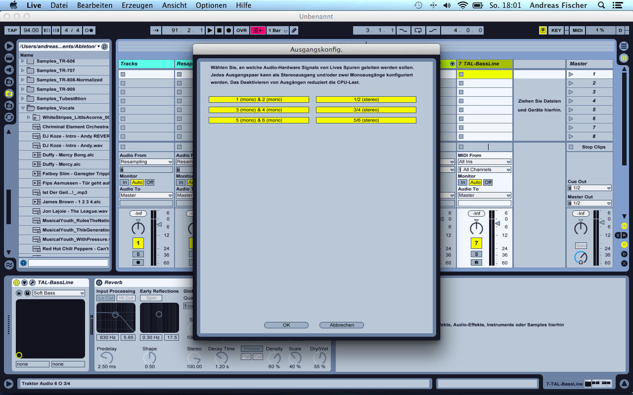
I had a simple clip running on a track and changed the Master Out settings a few times. Whatever I tried it only sent out real music (into my mixing desk) when I selected channel ‘1/2’ for Master out. 3/4 and 5/6 just kept being numb.
The problem behind all this is that the Audio device’s input settings for both channels 3/4 and 5/6 was set to ‘direct thru’. Meaning: Everything that is connected to the inputs is directly routed to the outputs. The device itself is not able to send audio data to these outputs in this case. Looking at it from a little distance it’s something I could have known before because every time I had Traktor Scratch running and attached the Audio 6 to my computer I was presented with a ‘direct thru’-configuration for both decks. I had to deactivate this every time I used it.
The solution is simple: Just open up the Audio 6 Control Panel and deactivate the checkbox for ‘direct thru’-mode. It’s probably a good idea to do this in the ‘startup’ tab since this changes the device’s configuration to behave like this automatically every time you connect it to your computer.
I don’t know if it’s necessary to do a reboot afterwards. While trying to find this solution I made so many of them I don’t know for sure.
Anyways: After making these steps I was able to select every possible input and output combination for my Audio 6 in Ableton – and all of them worked like a charm.
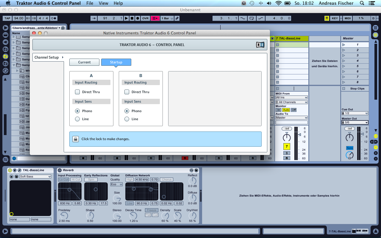
Using touchscreens for controlling other software (using TouchOSC, for example) one thing I always had my problems with was a missing tactile feedback. Using a hardware Midi-controller, for example, you don’t really have to look at it that much. many things just work because your fingers will find their way over the buttons to the correct knob.
This might not be the most sensible thing to do with a smartphone but… It helps. Once you find the correct slot your finger is automagically guided.
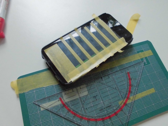
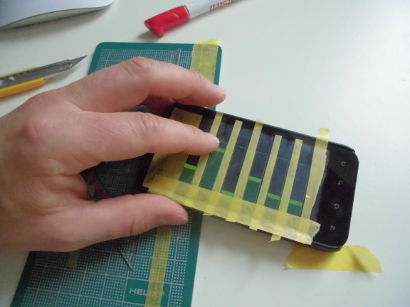
There are so many reasons why this is not the most sensible solution of all times but with the correct layout, proper spacing and some …
It just feels right. In the true sense of the word. Try it.
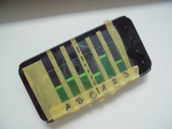
And you can take a marker to write on your smartphone. I like writing stuff on things.
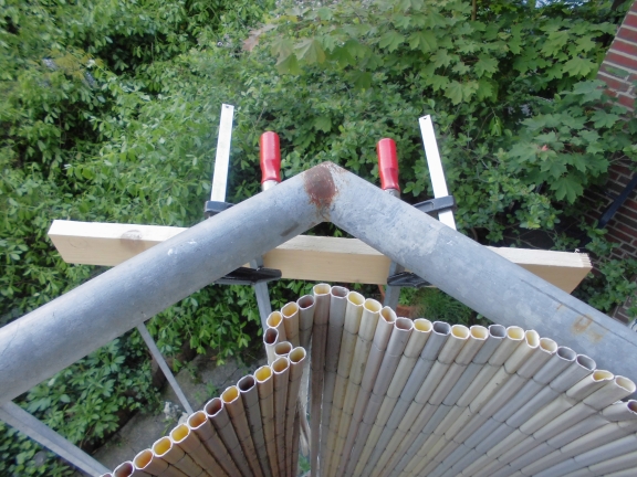
Ich musste neulich mal Kupferrohr biegen. 15mm Durchmesser, 1mm Wandstärke. An sich ja gar kein Problem, sofern man eine Werkbank hat. “Sofern”.
Da ist das Problem. Seit dem Umzug nach HH ist das mit dem Platz im Keller so eine Sache. An eine benutzbare Werkbank oder soetwas ist momentan überhaupt nicht zu denken, also muss improvisiert werden.
Nicht, dass mich das stört….
Das Kupferrohr hatte ich schon, es fehlte mir noch an einer geeigneten Biegevorrichtung. Normalerweise gehe ich immer ein paar Tage mit offenen Augen durch die Gegend und prüfe, was man so machen kann (eine Laterne vor unserer Wohnung scheint genau den richtigen Durchmesser zu haben…bevor da die Jungs von der Ordnungsmacht kommen, ist man schon wieder verschwunden).
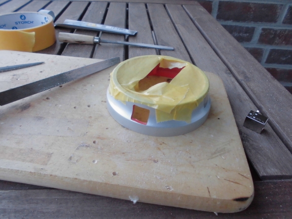
Aber wieso zum biegen eines Kupferrohres nachts eine Laterne misbrauchen? Viel angenehmer isses doch auf dem eigenen Balkon. Ein Stück Restholz und zwei ranzige Schraubzwingen bilden den perfekten Biegebock
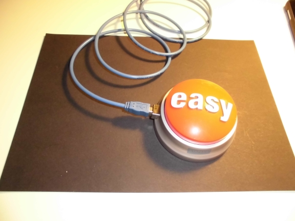
I guess everybody knows the Staples Easy Button.
[tube]https://www.youtube.com/watch?v=lkaAFObuUrA[/tube]
There are numerous hacks out in the wild adding some weird functionality to it. For quite some time I wanted to something similar. This is the documentation of how to make the Easy-Button a MIDI-USB device based on Atmega328 (Arduino).
Many hacks have in common that they are either relatively expensive (like…involving something with a dedicated teensy device) or rather ugly (due to holes just being sawed into the Easy Button’s case).
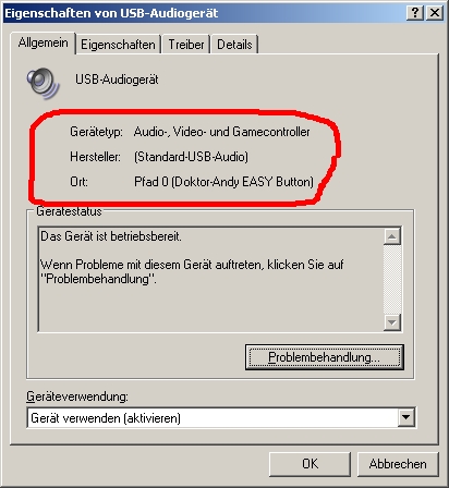
My first goal was to build a device that automatically identifies itself as an HID-compliant USB-MIDI device and gives simple MIDI functionality by using an Atmega328 and V-USB. In order to achieve a correct enumeration and to get a useful starting point I used the demo-versionof USBLyzer to get the necessary data from my KORG nanoKey and altered them in various places (Vendor ID etc..). (You will remember this one later.)
When the button is pressed a ‘MIDI Note ON’ signal is sent. Upon release it sends a ‘Note OFF’ message.
The second goal was to give it a clean overall look.
Let’s see…
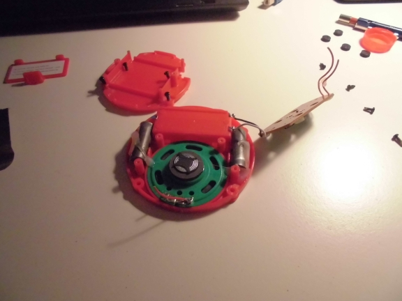
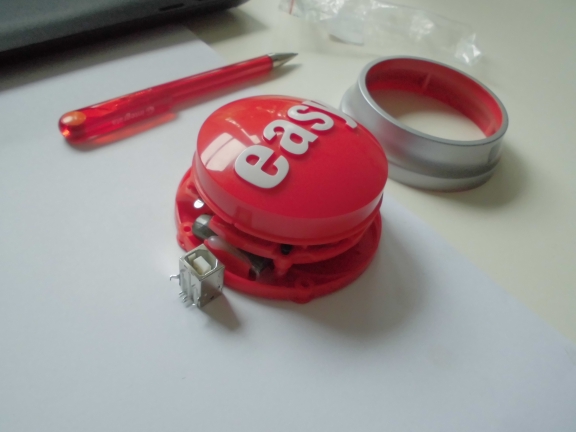
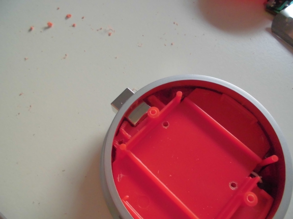
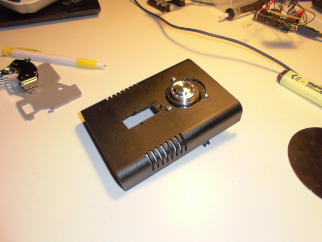
This is the Staples Easy Button with the cap and the clicker already being removed (which makes it just a pretty unidentifiable bunch of electronics and some plastic)
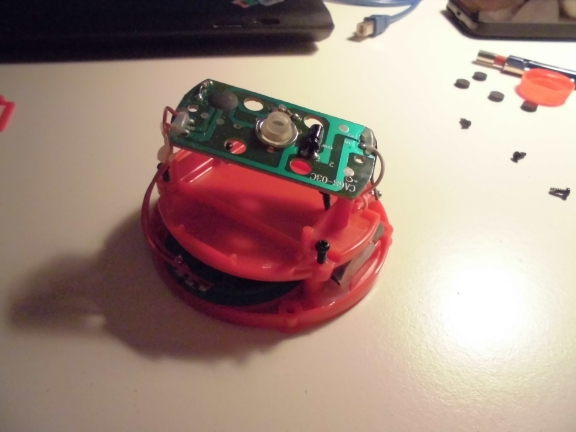
we don’t need the speaker so it will be gone soon….
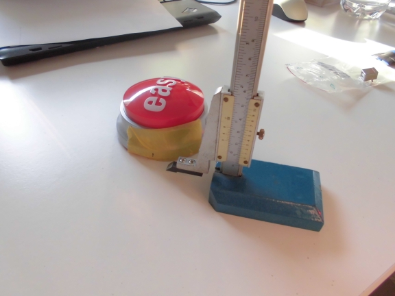
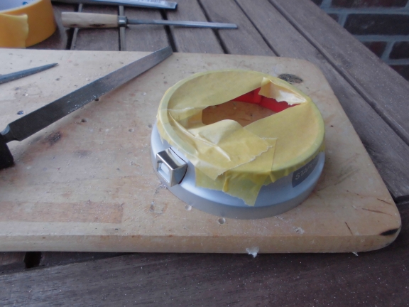
The black line shows how deep the cap goes when it’s pressed.
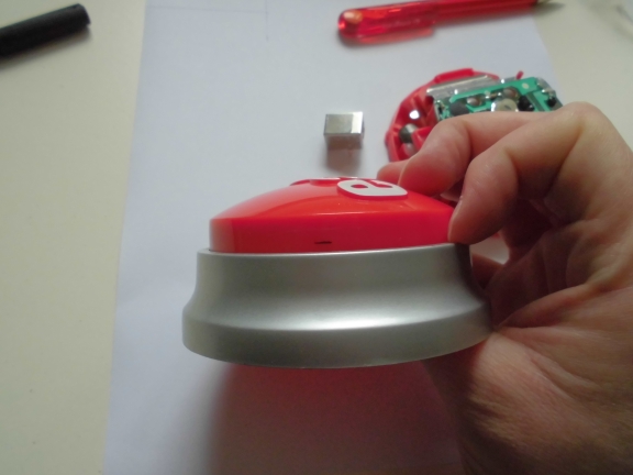
This is the spot where the USB connector will be placed
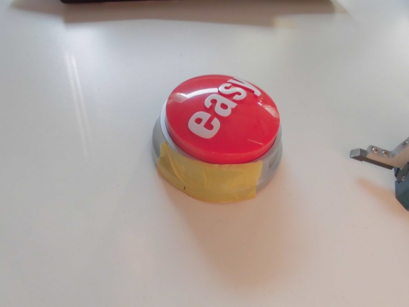
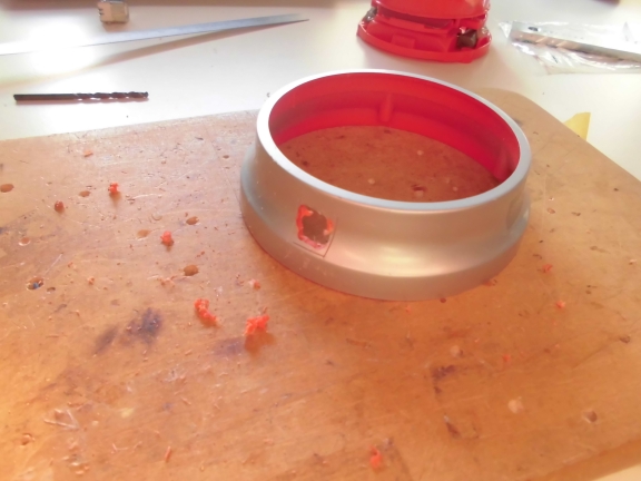
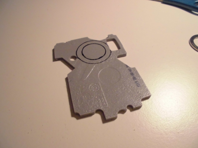
I might not be the best craftsman around (already mentioned that once before) but after some filing this one looks pretty decent:
The plastic on the inside has to be cut as well
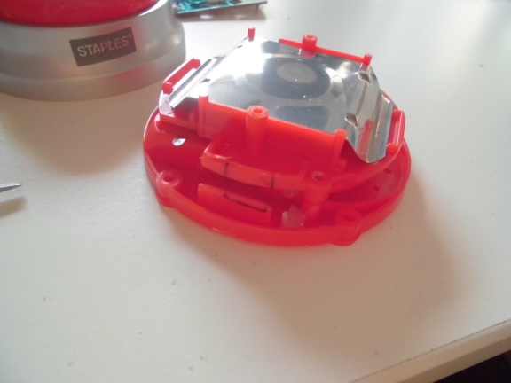
This DOES look quite well
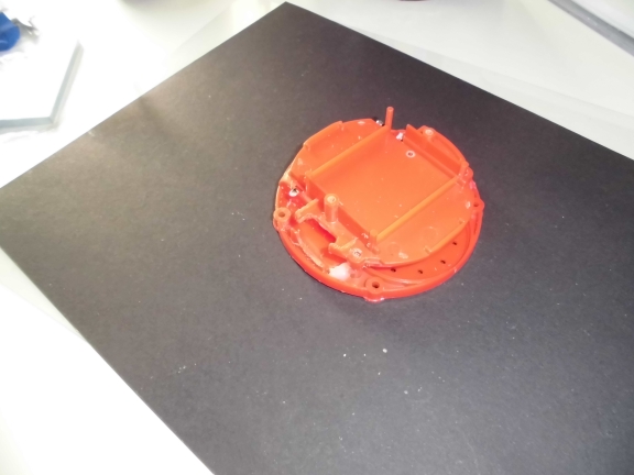
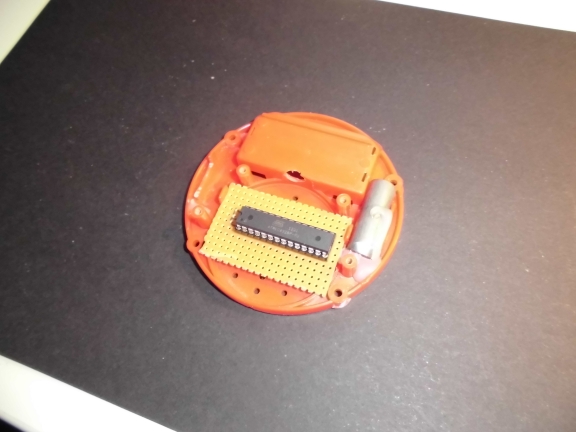
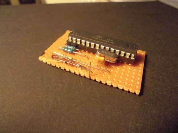
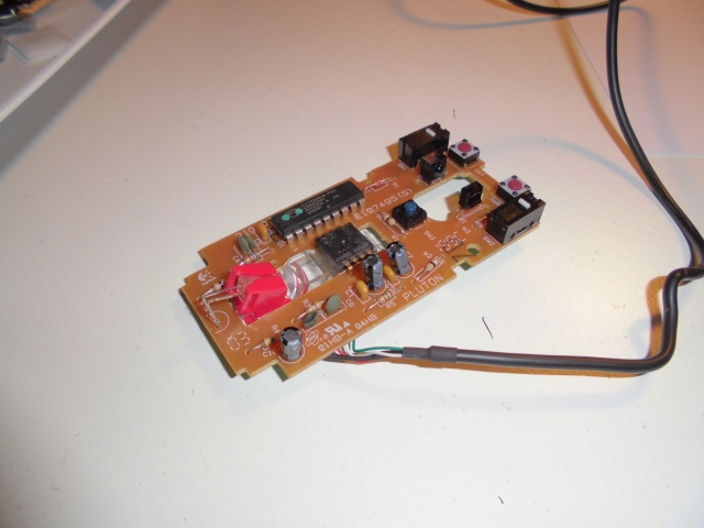
Now I need to add the circuit board. Due to the speaker being thrown out there is lots of space for that now.
The circuit is basically a 1:1 copy of the V-USB keyboard example. The Button is connected with data pin 6 of the Atmega. It involves some creative soldering of the diodes because I didn’t care too much about the circuit’s layout before I started soldering.
Everything’s coming to an end soon
It seems impossible for my camera to do any decent shots that contain the color red.
Anyway, you might get an idea of how the circuit fits into the structure.
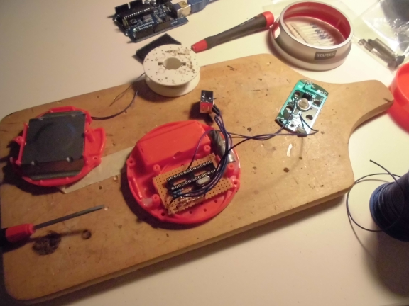
Some detail of how the actual button-mechanism is connected to the Atmega (the blue wires, you guessed it)
To make future additions a little easier I added an ICSP connector which fits nicely into what has formerly been the battery case
Finally… in all its glory.
I had this in the back of my mind for ~2.5 years now. Shortly before starting with this built I started wandering whether this might make sense or be worth the money or time invested or…..
F*CK IT. Never let doubts get in the way of your creativity. If this wouldn’t make sense than I probably wouldn’t have built it. Word! =)
The whole Arduino project (I did that arduino IDE 1.0.3) can be downloaded here. Unzip and copy the folder ‘Nanokey’ to the libraries-folder of your arduino IDE. Feel free to contact me if anything is left unclear.
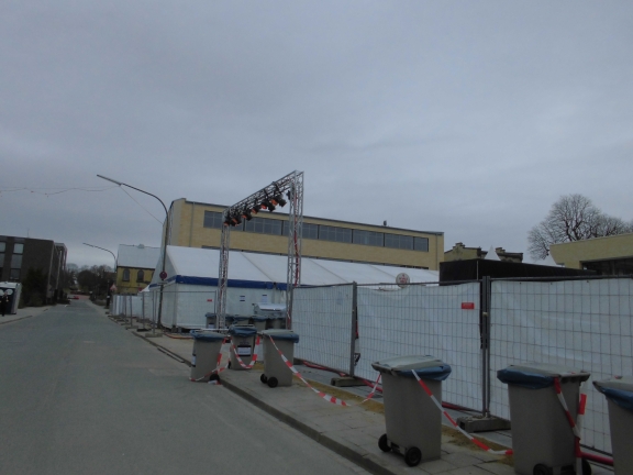
This post will be about my third time at the Terrassenfest (Facebook). It’s an annually held 3-day event organized by volunteers of the senior technical college in the city of Osnabrück. Every night there are 2 bands and a DJ afterwards. We are doing the stage for the third year now and I guess it’s the right time to go a little more into detail than the years before.
This is the 38th year this event takes place. Last year my former boss visited me when I was working there and told me he had been organizing this event ~25 years ago himself.
It all begins at home in Hamburg. I am in charge of lights and visuals and I will be using VDMX for the first time. I already created some footage and am working on the basic screen setup.
The stage-setup will contain 10 units of 42 inch monitors. 6 being twisted by 90 degress, hanging overhead in the truss, 4 being packed together in a somewhat classical 2*2 matrix-style stetup. The monitors themselves are configured in 3*3 matrix mode. This means every monitor gets the same input data but only displays 1/9th of the actual picture depending on the position that was set in its configuration.
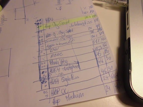
Codec shootout based on visual impression and CPU usage. VMDX’s new HAP codec won.
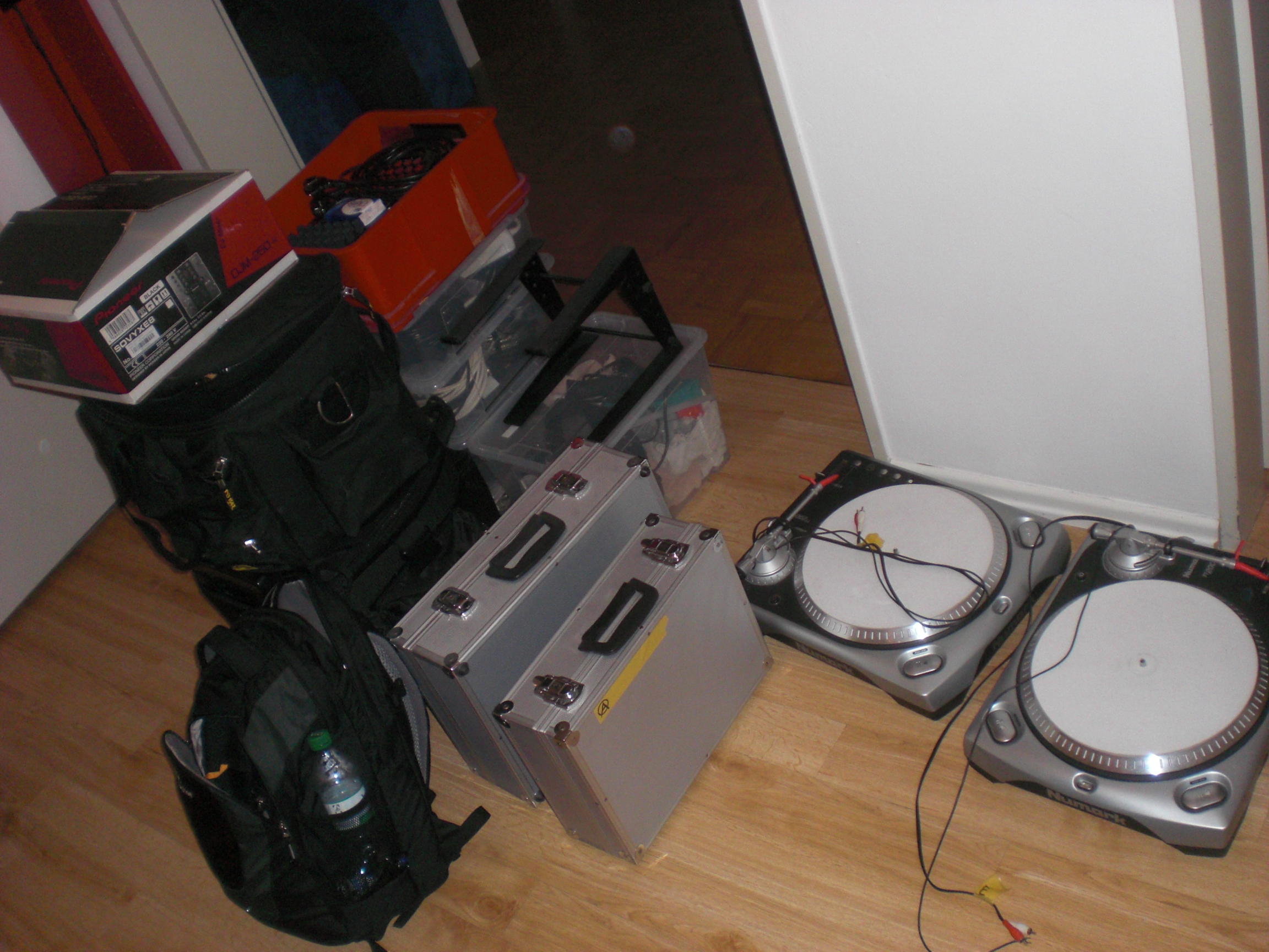
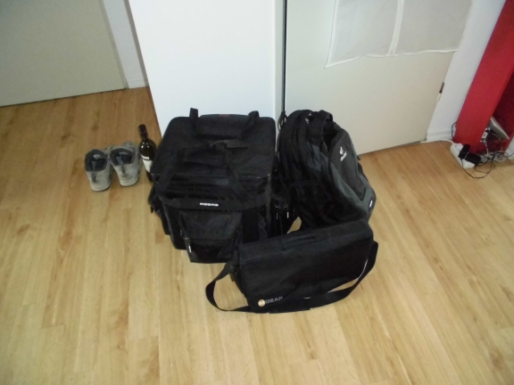
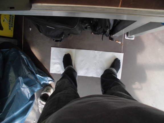
Packing my stuff for staying out of Hamburg for 5 days (sat – thur).
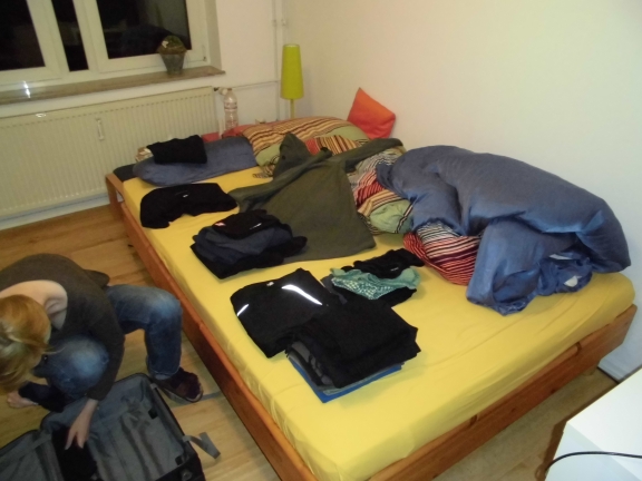
This is only the technical stuff i’m carrying:
MacBook pro, Lenovo Thinkpad, Akai APC20…. to name just a bit of the stuff i took with me. It’s important to know that I will be meeting friends of mine there and I’m planning to play arround with different stuff so I am taking way more than I’d need to.
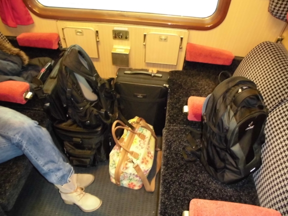
Entering a 4-day mayhem.
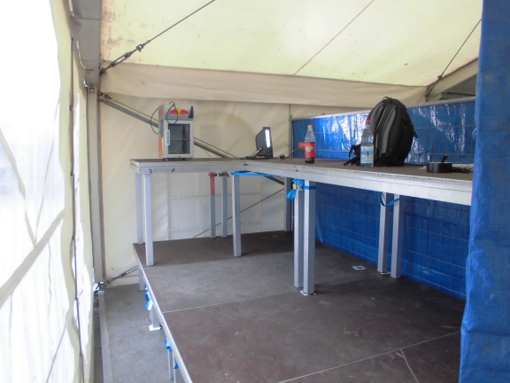
The foh (front of house) will be by new home from now on. The most important thing (the fridge) is already there. Though the Terrassenfest is organized by volunteers it doesn’t lack professionality at all. We get the best support one could think of. Including a never-ending amount of energy-drinks, beer and grilled food.
By the way: It’s one of the better ideas to use an extra cable only for the fridge at the foh. Trust me.
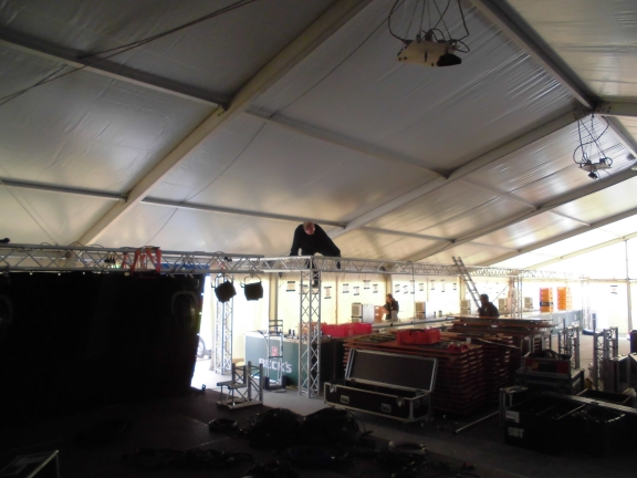
Working for the company doing the stage for me as the guy for lights and visuals also means: Bringing up the complete stage! From zero.
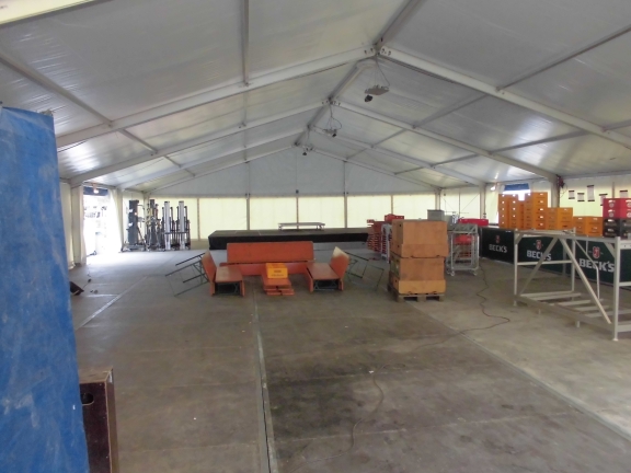
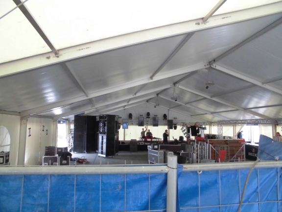
Well…. it IS that much. It took us Sunday to build up the stage.
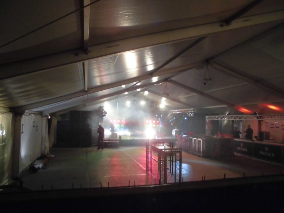
Yes, this is a friggin’ huge PA-System. It IS way too much for such a tent. But it DOES sound incredibly good.
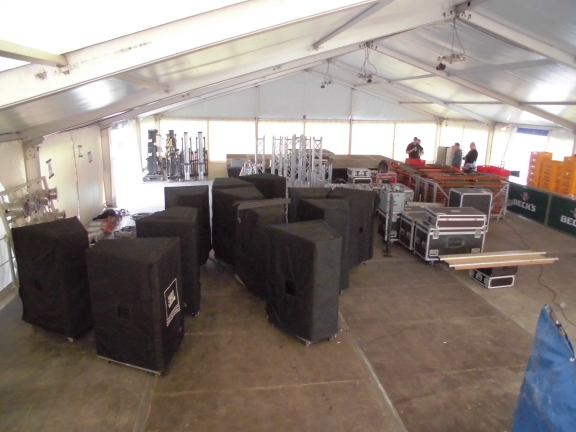
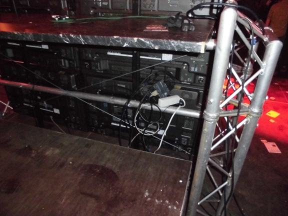
Part of the monitor setup. 4 Monitors are hanging in the back truss, one is hanging at each side.
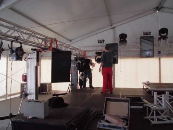
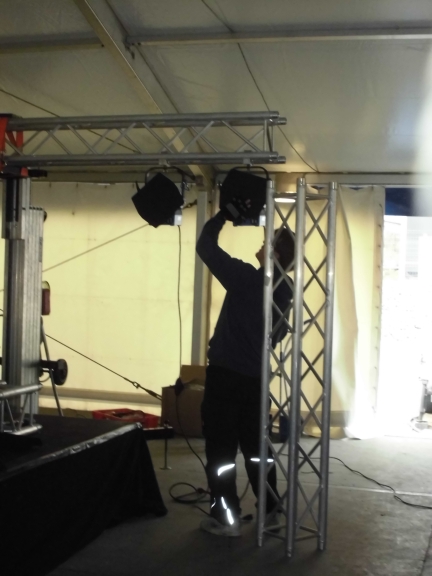
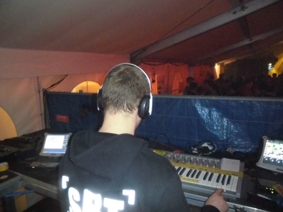
That might be me…
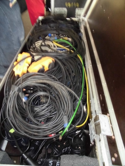
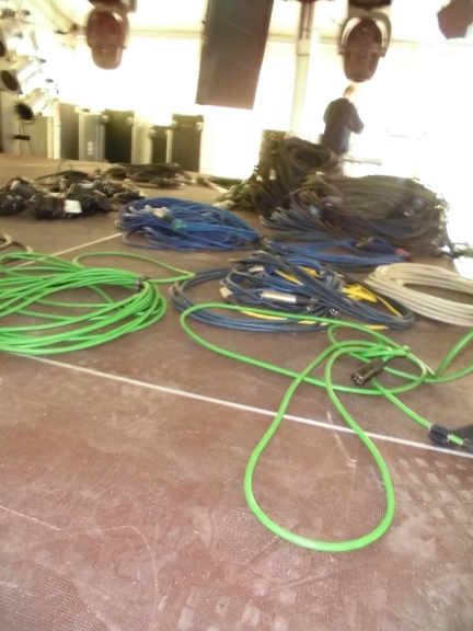
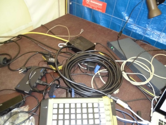
And that might be another pile of cables
Slowly growing
Oh… and by the way: we’re also doing the trussing and lights for the bar…
And YES: we are going full pro on this one.
First impressions at night. All lights on 100% to check whether we calculated our energy consumption correctly. We did.
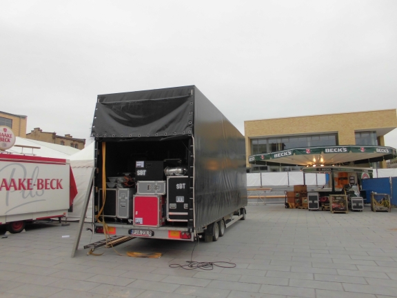
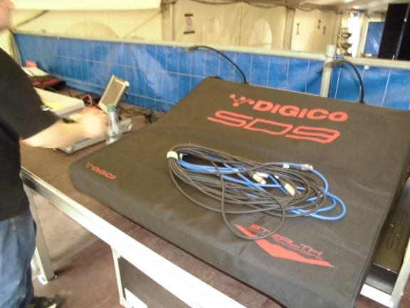
Getting a little bit into detail. The dmx data for the lights are transmitted via lumenradio. The video is transmitted via ethernet cabling based on Kramer technology.
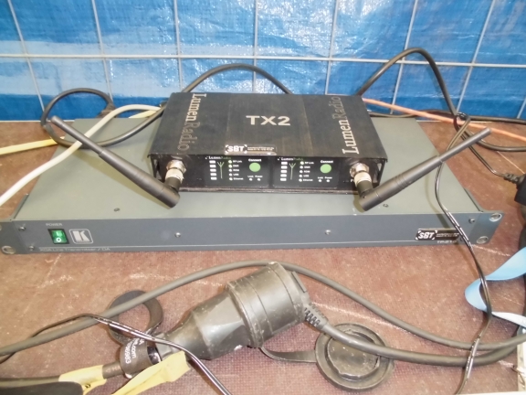
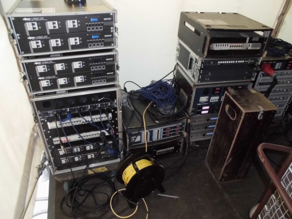
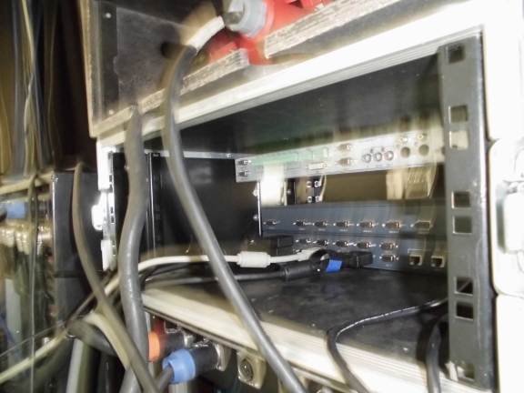
Signals arriving at Dimmerland, Amptown city. From here the DMX data are fed back into cable and the video data are sent to various multiplexers to reach the monitors.
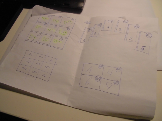
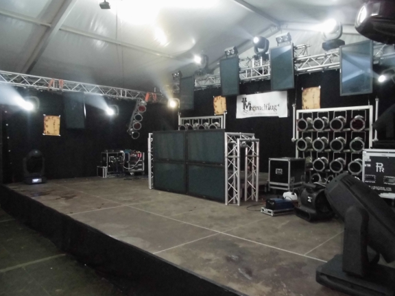
This is the final stage setup. The DJ booth will be put aside as long as the bands are playing. One aspect of this setup is to be able to change from band to DJ as quick as possible. It took us ~5 minutes each time.
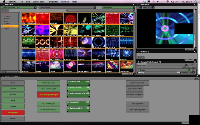
For the videos I created two main groups in VDMX. The ‘Truss-Group’ and the ‘DJ-Group’ (guess which is which). The Truss-Group consists of three layers: Background, Center and Front. The Background layer spans over the 6 monitors completely and the visuals will be twisted by 90 degrees. That’s okay since this layer is intended for blurry-motioned video backgrounds. The Center and Front Layer are twisted by 90 degrees within VDMX so they will be ligned up correctly on stage. Both layers are cropped and resized so the whole video of the layer will be shown on every screen.
The DJ-Group only consists of two layers: Background and Center but the configuration is similar – without the 90 degree twist.
I could have done more but I wasn’t too sure about overall CPU usage and stability so I decided to better be safe than sorry. Next time I guess I will be doing 8 layers each since VDMX showed no problems at all.
Everything that I wanted to have control of was connected with a custom control interface which was then connected to different midi inputs. That way everything stayed clear and easy to handle… just in case…
Everything is controlled via an APC20 from Akai
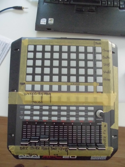
The buttons on the right select the page in the media bin (‘Chroma’, ‘Ballern’, ‘Stuff’, ‘Strahl’ and ‘Atmo’). The butons above the big stripe of yellow duct tape select the layer the video clip is played on and the 40 main buttons finally select the video clip itself. The faders from left to right control each layer’s opacity.
Btw.: The duct tape is the expensive type which is used by professional painters. Not the cr*p you get in your ordinary hardware-store. It’s 3 or 4 times as expensive but absolutely worth the money. You can stick it on, leave it there for a year or more and remove it without leaving just one bit of ugly residue. Try this with your Gaffa-Tape.
That’s my setup at the front of house. From left to right: MacBook pro 13″ running VDMX being controlled by an APC20 from Akai. Some earplugs and a Korg Kontrol 49 Keyboard for controlling GrandMa onPC running on a Panasonic Toughbook. If you look carefully you’ll spot a Wiimote as well. This was used to control two effects in VDMX. Pixelate and Strobe. Though I am generally not too much into using video-fx this sure was huge fun, especially for the people hanging around at the foh.
(click for a larger image)
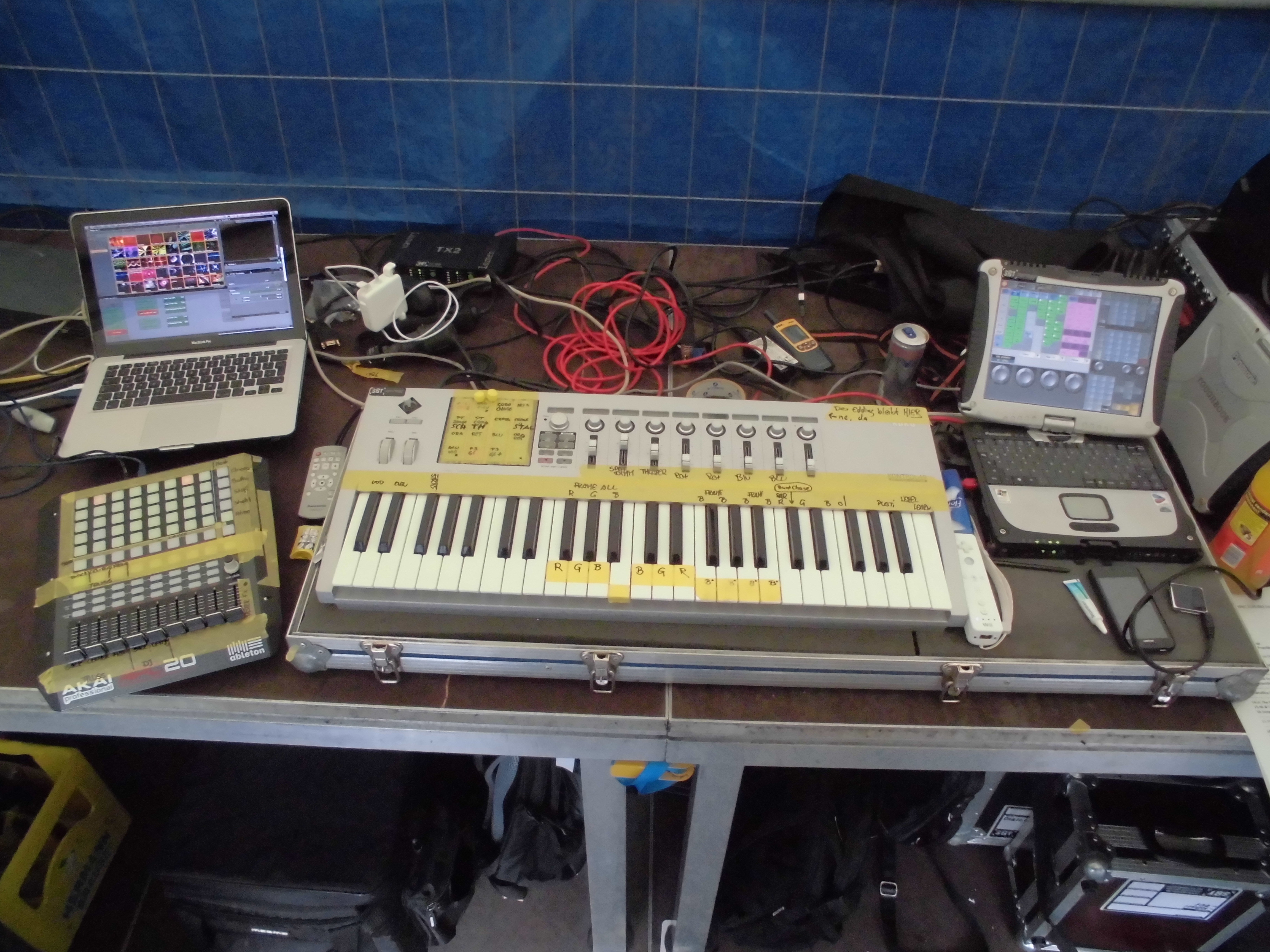
The way the lights are connected with the keyboard has grown over the years. It evolved from the very first show that I used when working in a discotheque. It has become so intuitive even my mom can do it:
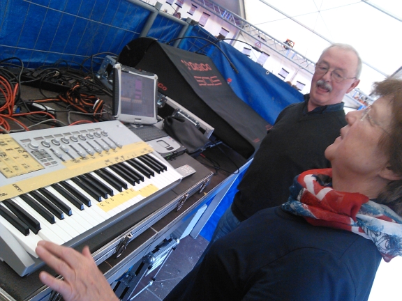
By the way: I was staying with my parents for the time which was quite a lot of fun. I moved out ~15 years ago and haven’t slept there more than 6 nights since. They brought me to the event every day and my dad was totally eager to carry my bag:
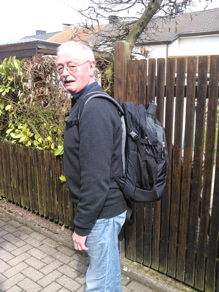
Considering the amount of bullsh*t (a.k.a infurious pain) he is going through with all his back this has to be accepted as one of the coolest things a dad can do for his son.
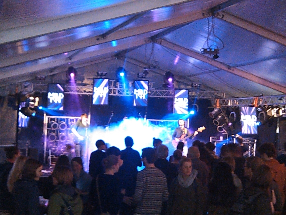
That’s part of what the setup is capable of:
This is one bad mobile-phone photo giving a glimpse of what it looked like when the bands played. During their set I brought their logos on the screen together with some background videos colour-fitted to the rest of the lights. This always looks amazingly cool and it shows that you don’t need an LED-Wall in the back to do a good show.
I will add more and better photos with overall impressions within the next days.
By the way: We intentionally didn’t use an LED-Wall. Right now I see LED-Walls on every yet-so-small village-party-stage. What’s wrong with the people out there? Is an LED-Wall the new huge phallus-symbol in stage design? Does every average top40-band really need hi-res image processing in the background? Wake up guys: It’s about the band and the music! Not about what you are able to dry-hire …..
Some hours into the first night (bands were done, DJ was playing) the event got into some trouble with local authorities because of noise. Fact is: we couldn’t get more silent than ~80 decibel just because of the people themselves making this amount of noise purely by being there. Anyways, It was on us to turn the music down. This ended in the situation that we needed the Master-Out on a headphone in order to -literally- hear anything from the music.
The second night we caught a glimpse of the music because the DJ turned his monitor speaker up enough so we could hear him through the tent. Foh seemed to be a good place to catch some … sleep. Cool thing: Nevertheless people stayed there until the end at 3’o clock in the morning. I was told there were ~3500 patrons every night.
Growing chaos at the second day.
Oh and by the way…..this is a f*cking NON SMOKING TENT….damnit
Revenge of a non-smoker
I learned from past events that it is important to NOT drink all the energy drinks that are available but only so many you really need to. Last time it took my body 5 days to come back to normal digestion…intervals….

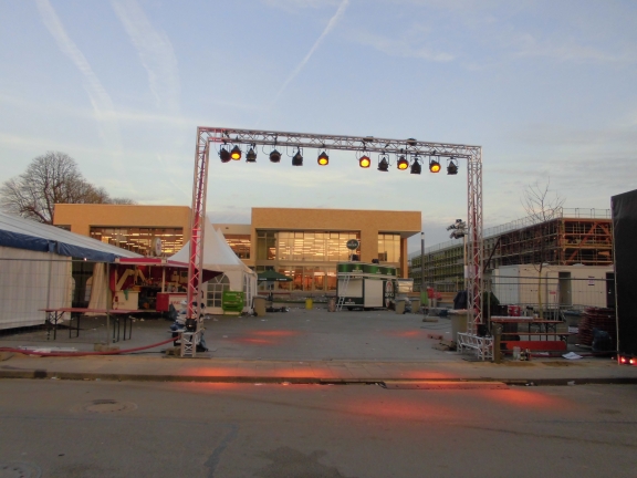
This is the event ground at the dawn after the last day. the event left its marks.
This is me going to bed after dawn after the last day after taking down the complete stage. Being all comfy and stuff. I guess the event also left its marks on me.

I am writing this right now so probably I’m not dead by Terrassenfest.
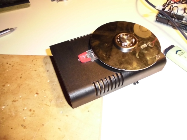
This is my attempt to build a Midi turntable (a.k.a. Jogwheel) from an old harddrive.
Some time ago I came across this (rather famous) article:
A hard drive hacked into a turntable
What they basically did here is to take an old harddrive and connect the motor via a set of op-amps to a microcontroller. When the platter is moved the motor (now actring as a generator) will produce signals that can be analysed by the µC and used for generating Midi out.
So far so excellent. But the deeper I got into the topic the more it became clear that this wasn’t the best solution for me since the article states that very small and slow platter-motion isn’t detected reliably.
That’s why I started building my own version of a harddisk turntable using the optical sensor of an old mouse.
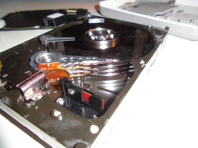
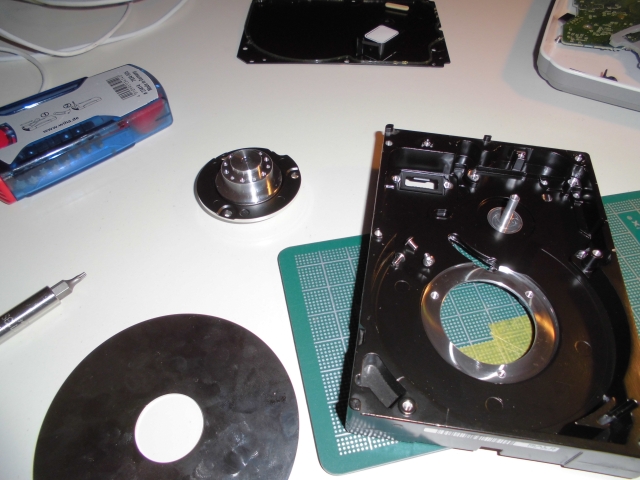
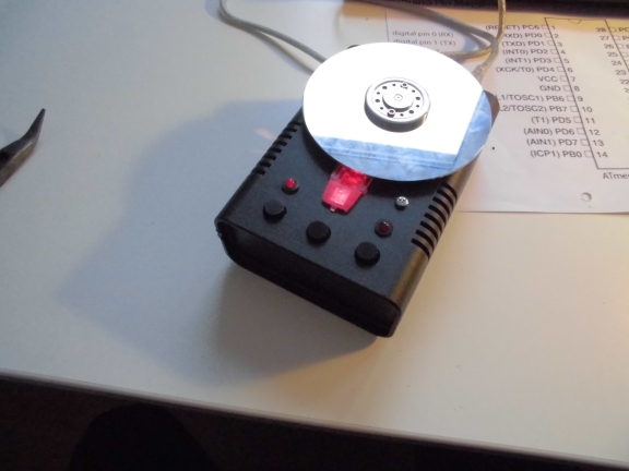
Here we go, it all starts with an old harddisk
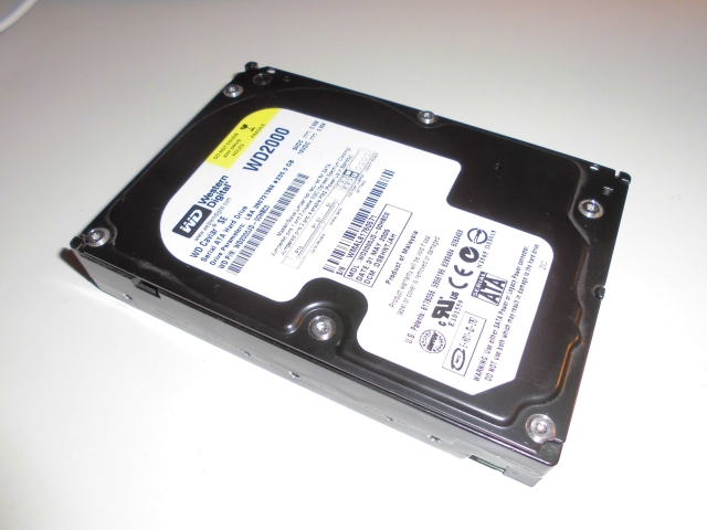
I have been dealing with computers for more than 20 years now but this is the only harddisk I had ever problems with. And this probably wasn’t caused by one of those “ooh my god…my harddisk suddenly crashed”-moments ismply but due to accidentally dropping it while moving to another flat.
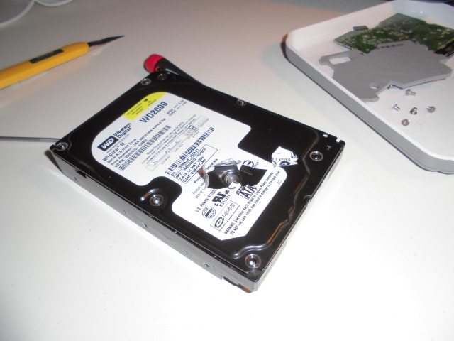
So – this is the first time ever that I’m taking apart a harddisk….
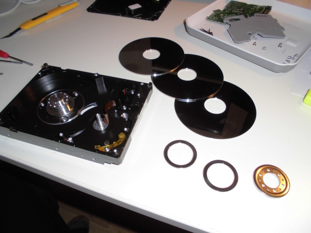
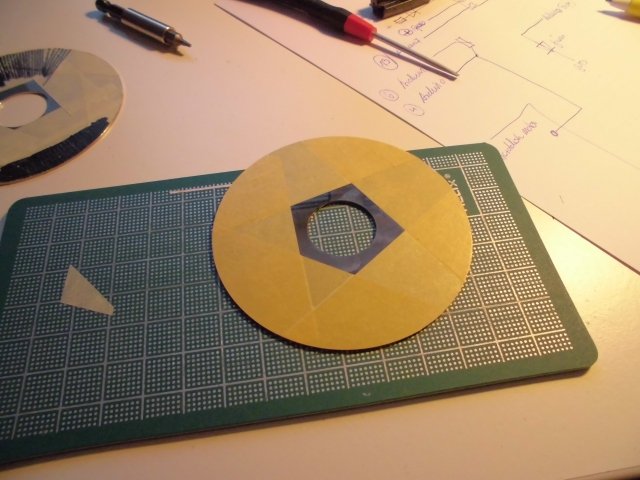
I figured out that I had to get rid of two platters because it would make the construction too heavy an dull-feeling.
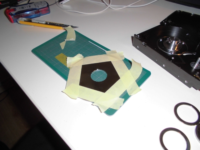
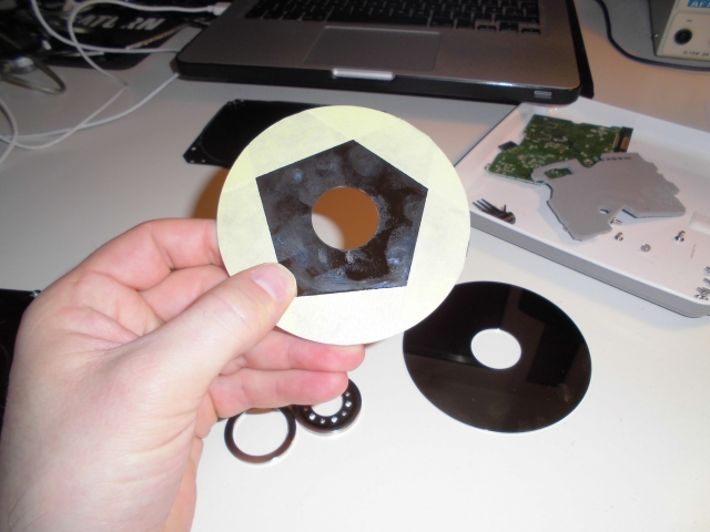
In order for the optical sensor to be able to detect the platter being moved I taped the edge of the platter to give it some structure.
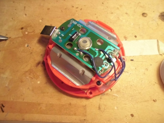
Fortunately the harddrive motor could completely be detached from the housing. This way I can use it in another case
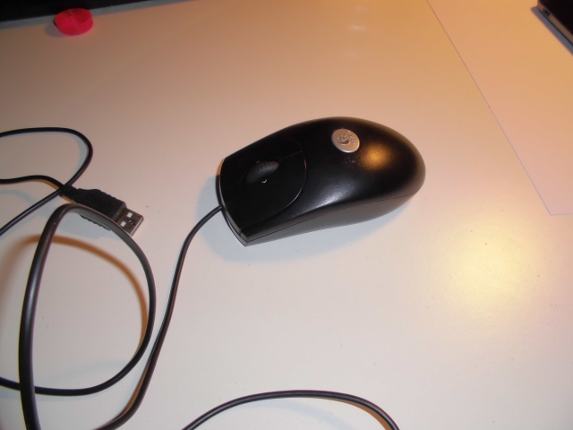
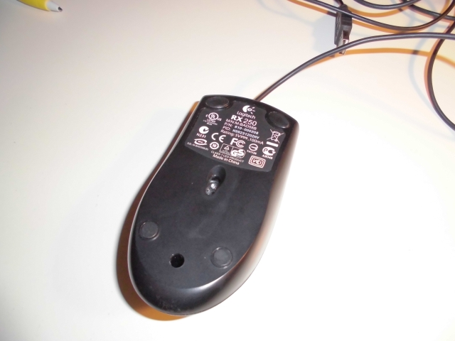
The mouse was a Logitech RX250 that I had lying around
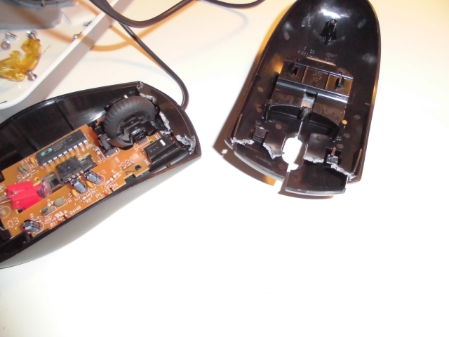
The sensor is of type A5020E. Fortunately I found an Arduino library for this device over here. It’s a little bit old and in order to make it work under Arduino 1.0.1 you have to exchange
#include “WConstants.h” against
#include “Arduino.h” in the .cpp file. That’s all.
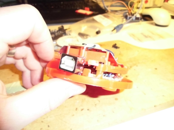
I simply desoldered the sensor and put it on a scrap piece of vector board. This will later be fixed by hotglue-influenced-technology =). the datasheet can be found here or here (if the original site will change or be offline).
During the first attempts I found out that it’s a good idea to keep the clear piece of plastic together with the mouse’s original LED in order to have the right conditions for the optical sensor’s illumination. For that reason I cut an appropriate hole into the new case.
It is pretty save to say that I am by far one of the worst craftsmen around….
Because I left away two of the three harddisk’s platters I had some space that needed to be filled up. This piece of foam comes from inside the old harddisk
Some hotglue later
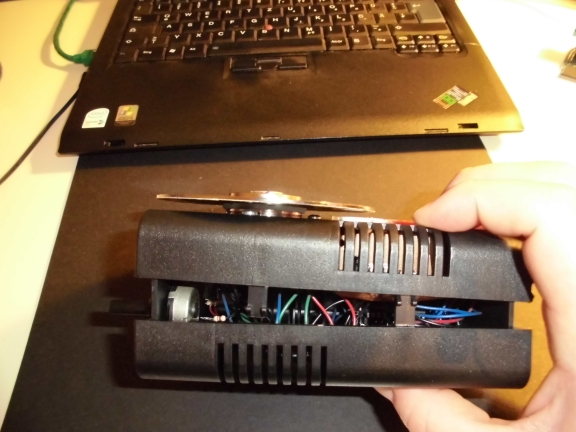
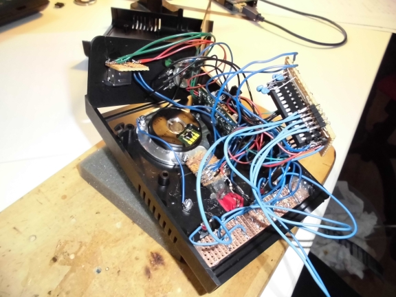
At the moment the circuit only exists on an Arduino breadboard. I will fix this later
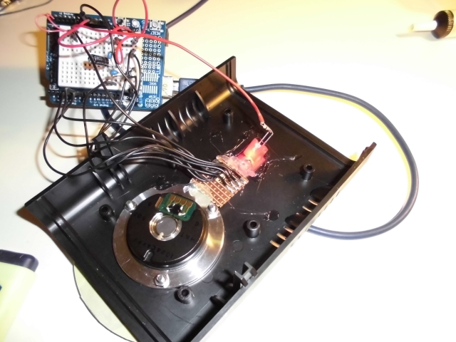
Proof of concept
Normally I try to create all my circuits as clean as possible. Proper layout, exactly the right amount of space, everything neat and tidy. Not this time. I think that from now on I don’t give a brick about that any more. It’s way more fun to just go for it with as little space left as possible. Trains your soldering skills as well.
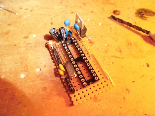
I could’ve left the voltage regulator since it only causes problems. There isn’t even a reason for it since the device will be USB-powered and USB has relatively exact 5 Volts so why care… anyway, I didn’t want to desolder it… yet.
The USB interfacing is done via one of my all time favourite hacks. I once bought about 15 ultra-cheap USB-to-MIDI convertors (~6€ each) and I use one everytime I need USB-Midi in one of my Projects. (Those where you only have a cable with USB on the one and two MIDI conectors on the other side. In between is a circuit taking care of all the USB stuff etc.)
While doing the finetuning I tried different approaches for the coating of the platter. An untreated harddisk platter’s motion will not be recognized by the optical sensor so you have to attach some kind of structure to it.
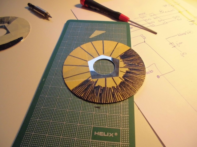
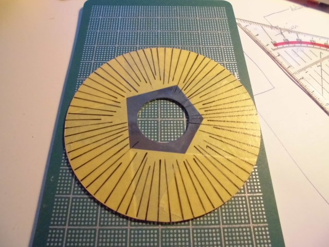
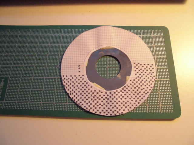
Using plain simple duct tape I was able to yield the best results. The rest will be handled in code.
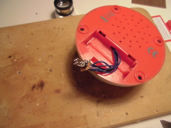
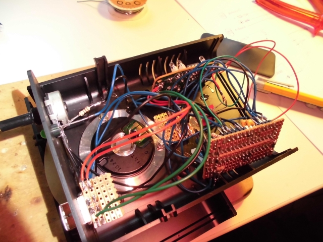
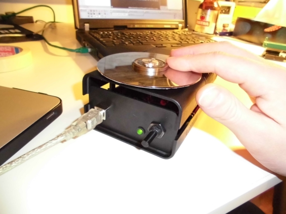
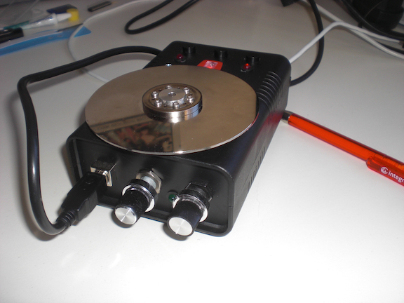
And just as a little side gimmick i added a green led which is lit …
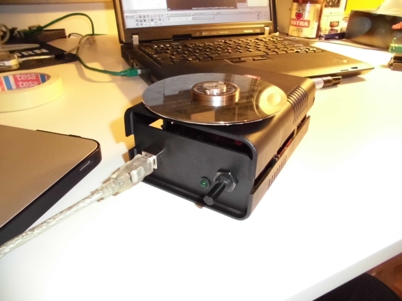
…when you touch the platter. Oh – and it sends out MIDI by the way =) The poti is there to adjust the sensitivity of the touch sensor.
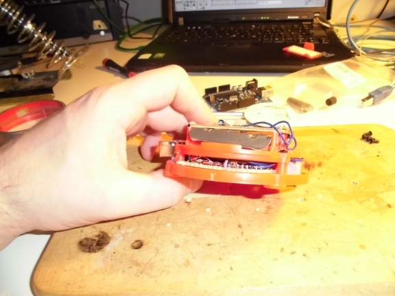
This picture shows the distance between the platter and the optical sensor. I tried different configurations but it turns out that my initial approach was just about perfect.
While thinking about how to actually use this thing I came across a few ideas and added a little more stuff to the circuit
Pressing the left putton will light up the left LED and make the device put out Midi CC #42 when the platter is spun. When the right button is pressed the other LED will light up and Midi CC #43 will be sent upon moving the platter. When the middle button is pressed the Midi Channel will change from 9 to 10 so you can use it for temporary pitchbending, etc. The screw above the LED on the right side is electrically connected to the platter so you have another ‘platter is touched’ contact.
The whole device came out pretty well. I still have some minor quirks when spinning the platter ~really~ fast but I will give it a test run within the next days before altering the code any further.
[Update 10.11.2013]
I added another poti which makes it possible to change the response rate of the platter (and, of course, I altered the micro controller’s code…). That way you don’t have to fiddle around within software but can easily adjust it on the fly
As a result I found a quite easy to do live video scratching within my favorite VJ-software (VDMX)