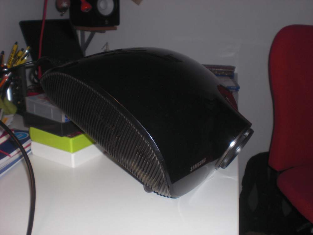
Okay. Next try on projectionmapping. I already experimented with this a while back but didn’t come very far.
For now, some well-meaning soul equipped me with a used projector. First Thing: put it in the right Position.
Okay. Next try on projectionmapping. I already experimented with this a while back but didn’t come very far.
For now, some well-meaning soul equipped me with a used projector. First Thing: put it in the right Position.
Seit kurzem bin ich glücklicher Besitzer eines Magic Arms (Ich schrieb darüber). Das Ding wird verwendet, um beim VJ’ing einen MidiFighter irgendwie passig positionieren zu können. Was noch fehlt ist eine Halterung für mein altes Handy, das per TouchOsc noch einige zusätzliche Steuerelemente zur verfügung stellt.
Auf geht’s:
Natürlich soll der Halter aus dem 3D-Drucker herausfallen. Fertig gibt es sowas nicht, am Rechner konstruieren ist möglich, nervt aber. Außerdem wollte ich eine Idee ausprobieren, die ich schon länger mit mir herumtrage.
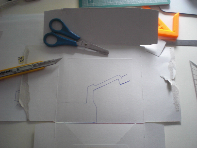
(Ja… ich bin ein 37 Jahre alter Mann und verwende eine Kinderschere, schön mit abgerundeter Spitze, damit ich mich nicht verletzte … jajaja … Papier stresst mich einfach)
Ganz großartige Nummer. Seit geraumer Zeit habe ich hin und wieder einen Visual-Gig im Rosenhof Osnabrück. Bevor ich nach Hamburg gezogen bin, habe ich 10 Jahre in direkter Nachbarschaft gewohnt. 1986 mein erster Kinobesuch (damals war’s noch … ein Kino): “Didi auf vollen Touren”. Mit Mama. Klar, dass ich erst 250km wegziehen muss, damit sich was ergibt. Meine Bookings sind eben antizyklisch. Isso.

Es HAT einen auf eine gewisse Art und Weise kruden Charme. Is’ aber egal. Der Vibe stimmt. So richtig.
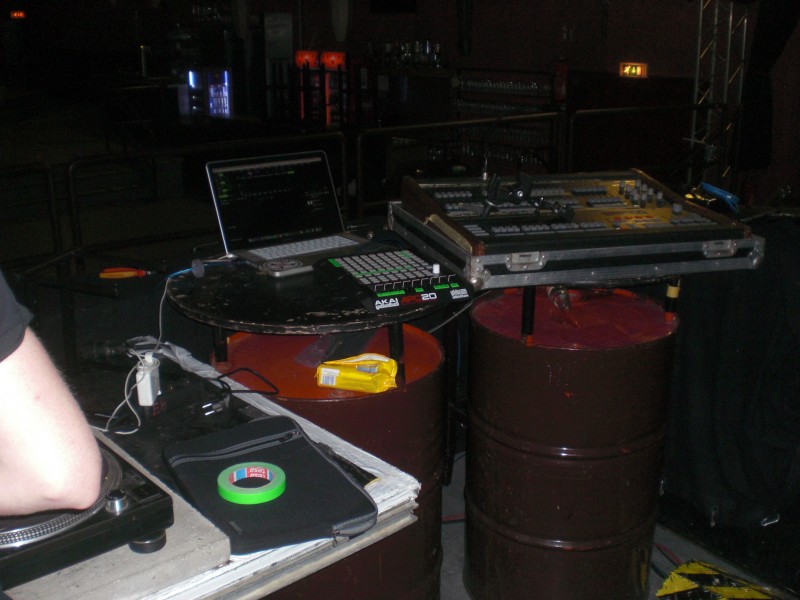
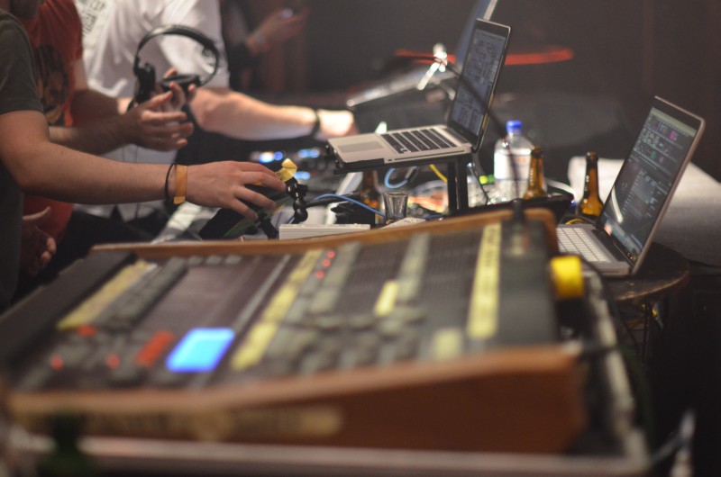
Am Pult sind wir in der glücklichen Lage, uns so richtig austoben zu können. LightCommander für’s Licht ist jetzt nicht das aktuellste Pult, verrichtet aber anstandslos seinen Dienst. Ich war kürzlich zu Besuch bei den Leuten von MA-Lighting und kann guten Gewissens behaupten, dass das hier nichts ist, wofür man sich schämen muss. =) Die zwei MacBooks für die Visuals hingegen sind absolut (ab-so-luHut) notwendig. Ich benutze VDMX und gehe per SyphonTCP in den Rechner des Haustechnikers, der die Visuals per Resolume konstruiert. So haben wir beide was davon, Er hat das letzte Wort und ich kann als Externer auch früher abbauen, um z.B. den ersten Zug zurück nach Hamburg zu kriegen (zu den Eindrücken einer vermeintlich ungestörten Zugfahrt Sonntag morgens um kurz vor fünf schreibe ich dann demnächst mal etwas).
Mein aktuelles Set kann komplett per Midifighter gesteuert werden. Mit den Wiimotes wollte ich noch ganz viele lustige Sachen machen, die APC20 steuert Resolume auf dem anderen Rechner. Über das IPad wird eine GoPro ferngesteuert, die ~irgendwo~ versteckt ist.
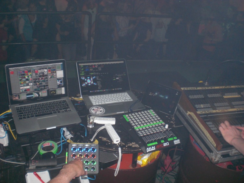
2 Leute für Licht und Visuals, 2 Leute für die Musik: 4 Rechner.
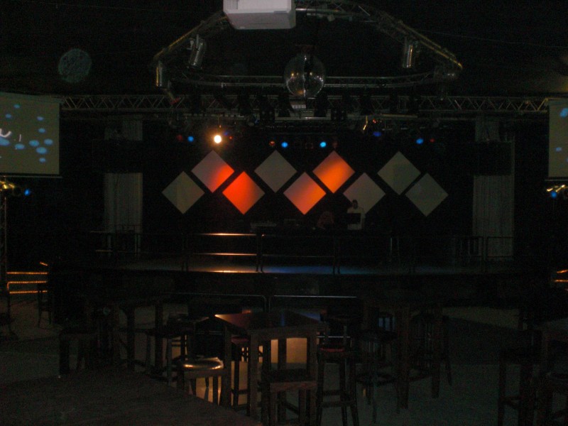
Und hier sehen wir Osnabrücks derzeit geilstes Video-Setup (Juni 2015). Ich bin technisch nicht ganz unschuldig daran (“3 Beamer steuert man am besten soundso”), aber Dominic vom Rosenhof tobt sich hier gerade richtig aus. Ehre, wem Ehre gebührt.
9 Panels im Backdrop dezent angestrahlt per Par64-Orange. Schlimmer geht eigentlich nicht, aber selbst das hat schon die ersten positiven Kommentare erzeugt. Links und rechts normale Leinwände. So haben wir es gelassen, bis angenehm viele Gäste da waren.
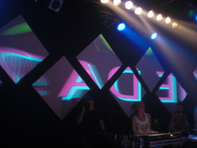
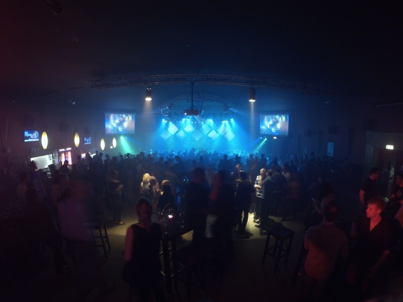
Dann Licht aus, alles dunkel, passende Musik und … Feuer frei. Hach, wie fein.

(Bitte im Hinterkopf behalten: 90er Party. Die Visuals sind also absolut auf den Punkt….)
Für Leute, die sich mit Visuals auskennen, ist das Mapping auf 9 Panels jetzt nicht das allerallerkomplizierteste auf der ganzen Welt, aber es haut einen trotzdem um. Weil es obergeil ist. Und streng genommen ist es auch für Leute, DIE sich mit Visuals auskennen, gar nicht so trivial. Mach’ das mal ohne Madmapper. Und dann bitte so, dass man die Deckkraft jedes Panels einzeln Regeln kann. Und alles mit Footage, deren Auflösung größer ist als 640*480. Und alles ohne Ruckler.
Vermeintliche Profis werden jetzt anmerken, dass es im Vidvox-Forum einen 12-Quad-ISF-Effekt gibt, der genau das ermöglicht. Genau. Dann rate mal, wer den programmiert hat.
This project is based on the idea of my buddy Matthias over at Visual Phi Events. The idea is simple: “Let’s do something with a Theremin controlling visuals. That’d be cool.”. Well, it surely is…
Fortunately we didn’t have to buy an original Theremin (for the price of an original Theremin) but could base our idea on the work of the Open Theremin Uno project.

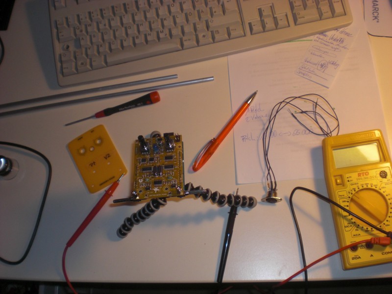
Adding Midi to the Theremin circuit is as easy as soldering 3 wires to the board. Since it’s all based on the Arduino Uno it’s easier to link to the article on the Arduino website than writing it down myself.
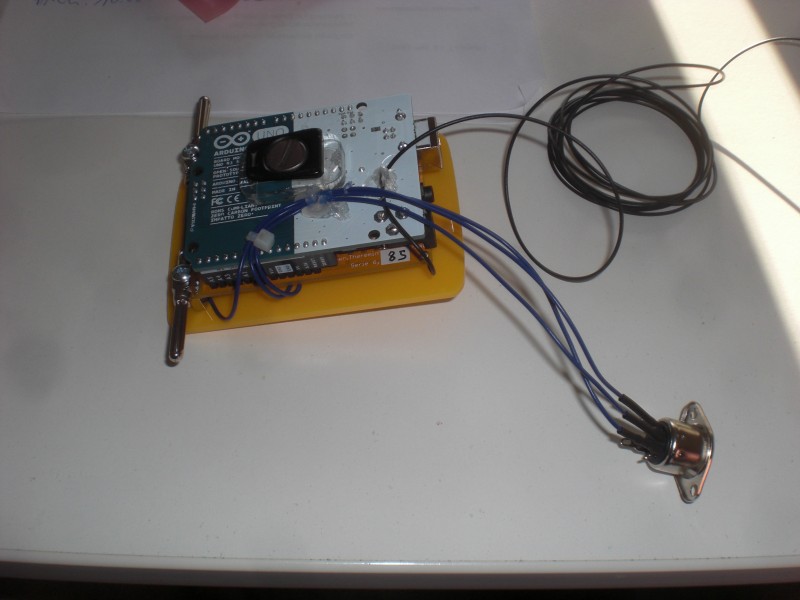
For the first basic tests I connected the Theremin to a simple zoom-effect in VDMX:
The finished project was set up at the Sabinchenfest in Treuenbrietzen.
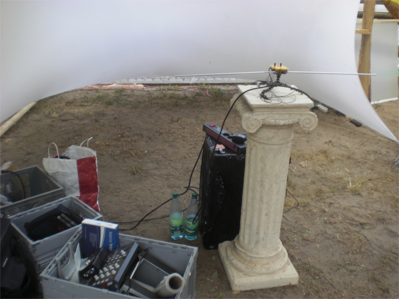
The two possible Midi data-streams (one corresponding to the Theremin tone’s pitch, the other one to the volume) were connected with a simple Quartz-Composer patch, controlling the angles of a cube. That was cool.
Walimex Magic Arm. Geiles Teil. Manfrotto Superclamp dabei und es macht richtig Spaß.
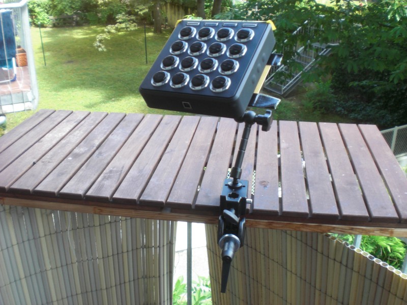
Damit der Midifighter drauf hält, habe ich aus Platinenmaterial (umbeschichtet, hatte ich noch herumliegen) eine Basisplatte gebaut
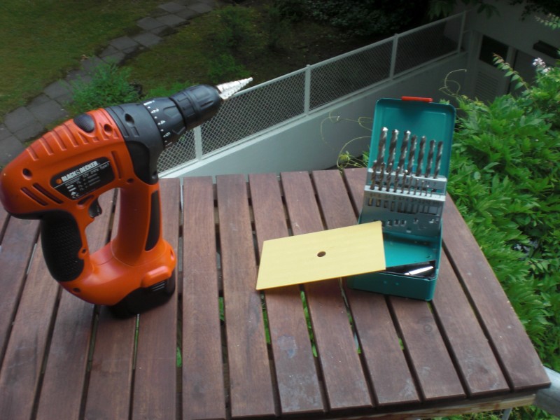
“Gebaut” bedeutet in diesem Kontext: Loch gebohrt. Huiii. Noch einen Hauch Gaffa als Kantenschutz dran. … Nahezu perfekt. Der Midifighter wird in diesem Fall einfach mit seinen Standfüßen an der Platte eingehakt.
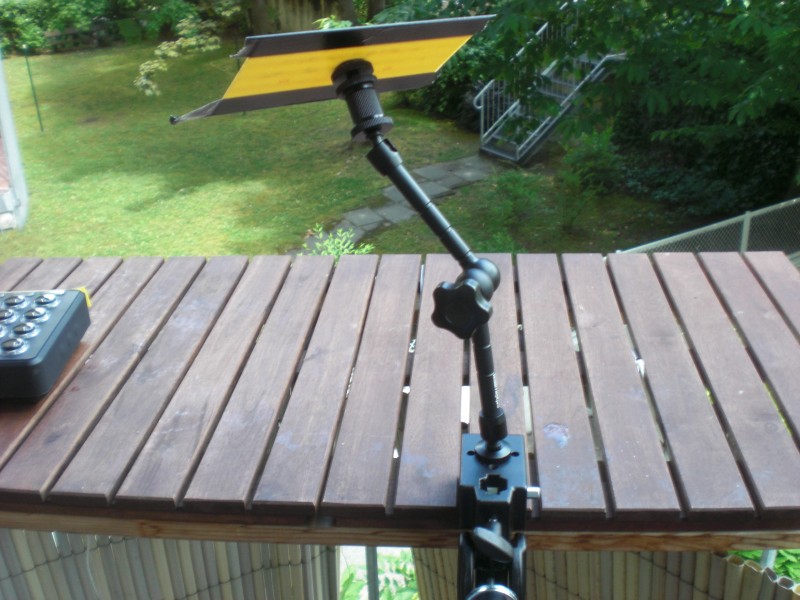
Der erste Einsatz hat gezeigt, dass es noch Verbesserungspotenzial gibt. Die Schraubverbindungen sind so stabil, dass sie zwar bombenfest halten, sobald man aber die Trägerplatte einen Hauch bewegt, ist alles sofort locker. Alu halt. Habe erst überlegt, mit Schraubensicherungslack beizugehen, das war mir aber zu unflexibel. Gegebenenfalls. will man ja auch auf einem Gig fix irgendwas umbauen/ ausprobieren. Versuche mit ‘Polstern’ aus Papier, das ich mit Gaffa umwickelt habe, haben auch nicht den gewünschten Effekt gebracht.
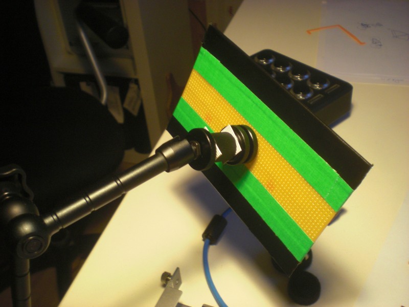
Flachbandkabel scheint zu klappen. War eigentlich eine Schnapsidee, funktioniert aber prächtig (und ein halber Meter Deichkind-Gedächtnis-Klebeband ist bestimmt ebenso ein maßgeblicher Faktor – na klar doch).
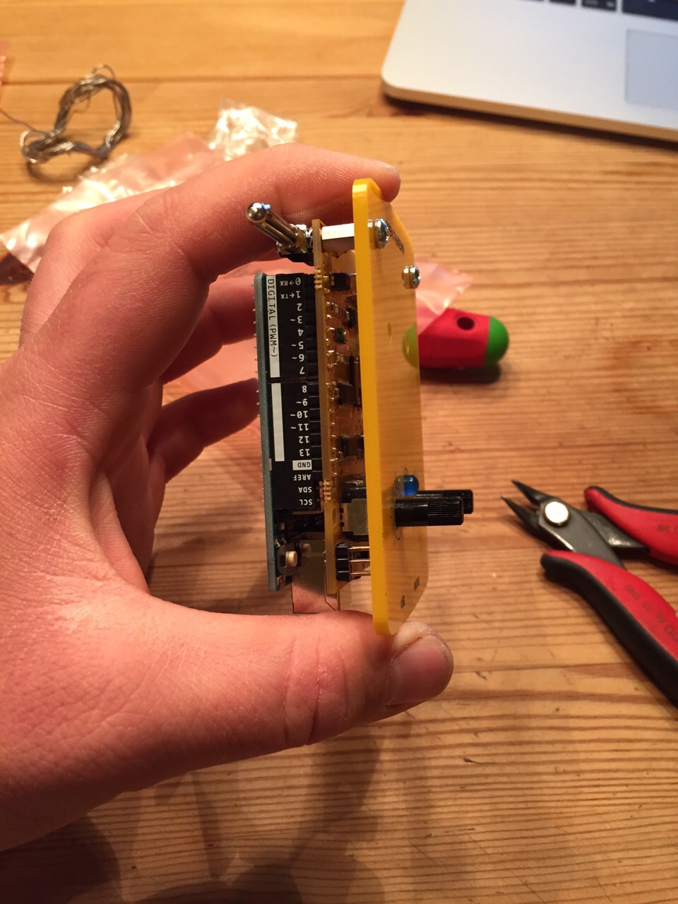
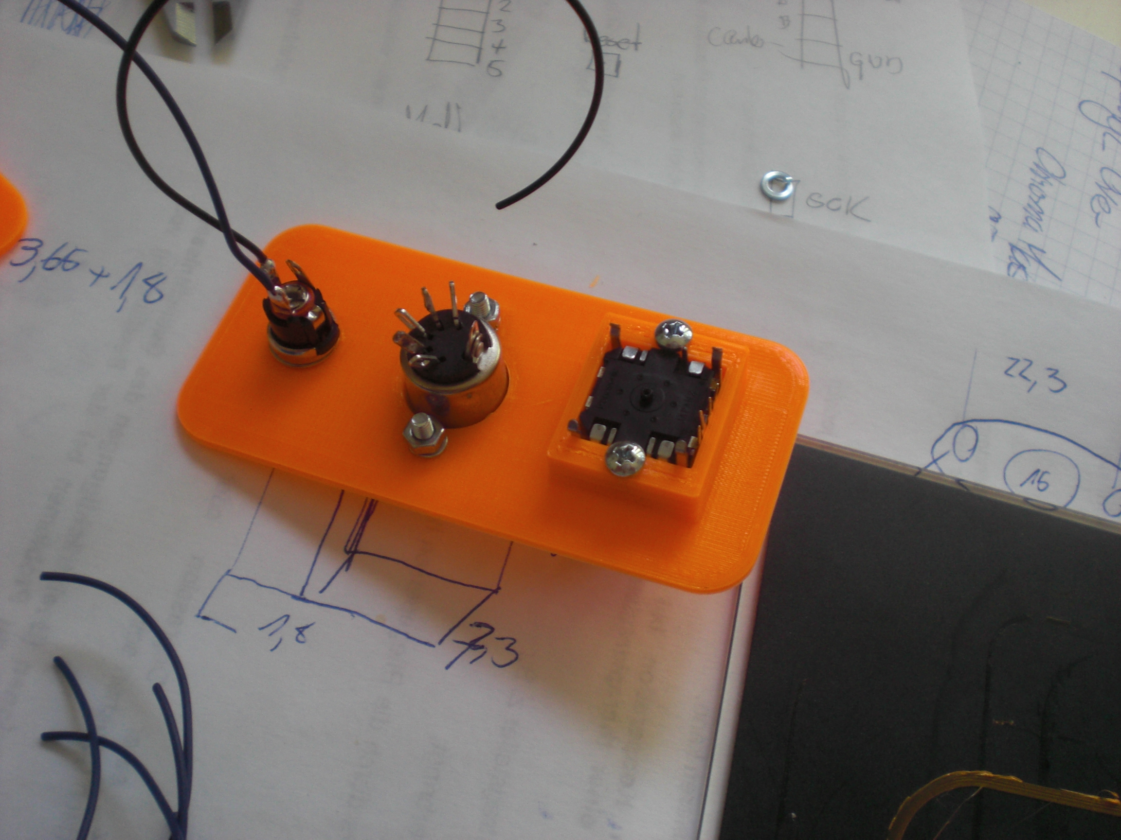
An idea that came up during the 31C3. The guys from VisualPhi had some motion sensors lying around and wanted to use them to control their VJ-software. That’s why I built them a Motion-Sensor-to-MIDI-Converter.
As usual it all starts on a breadboard. Most of the times I draw the schematics parallel to building the circuit on a breadboard. Guess that’s the usual way.
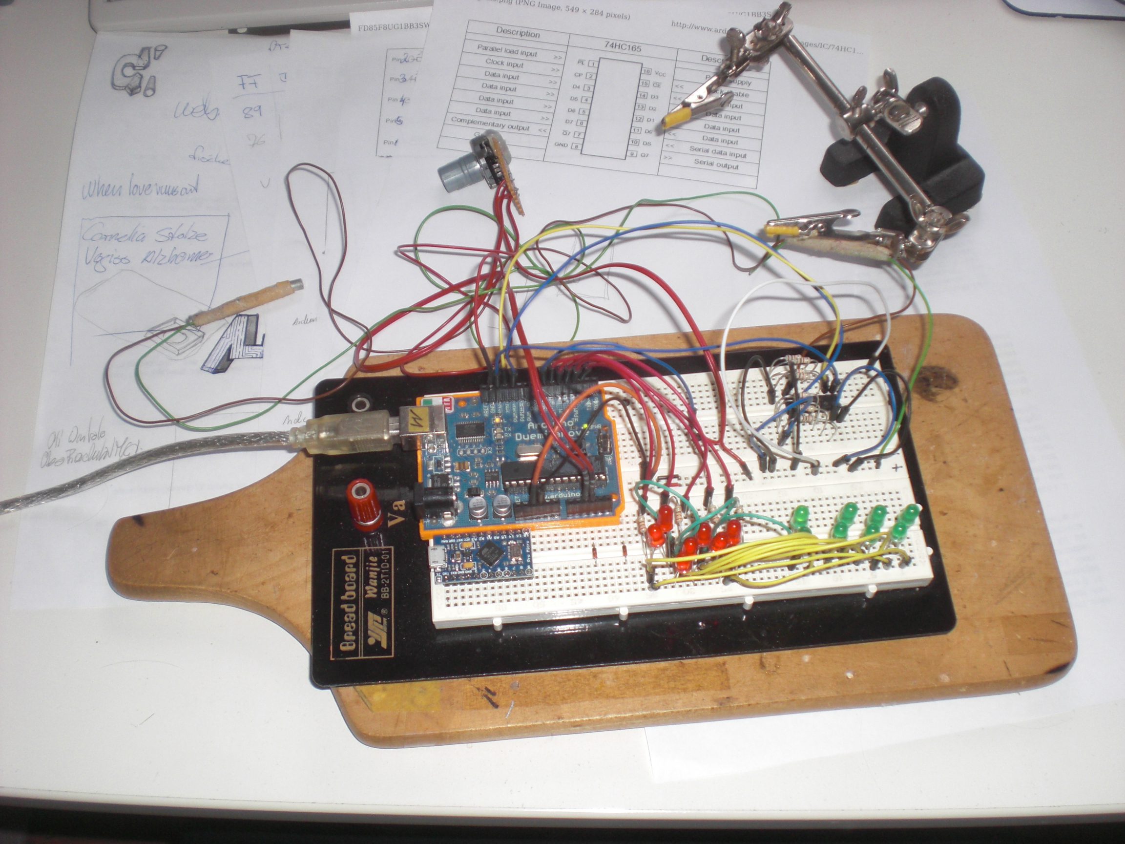
The circuit itself is rather unspectacular. 8 inputs are polled from a 74HC165. Then there’s a little bit of logic implemented within an Arduino and then there’s 16 LEDs, a rotary encoder and MIDI out.
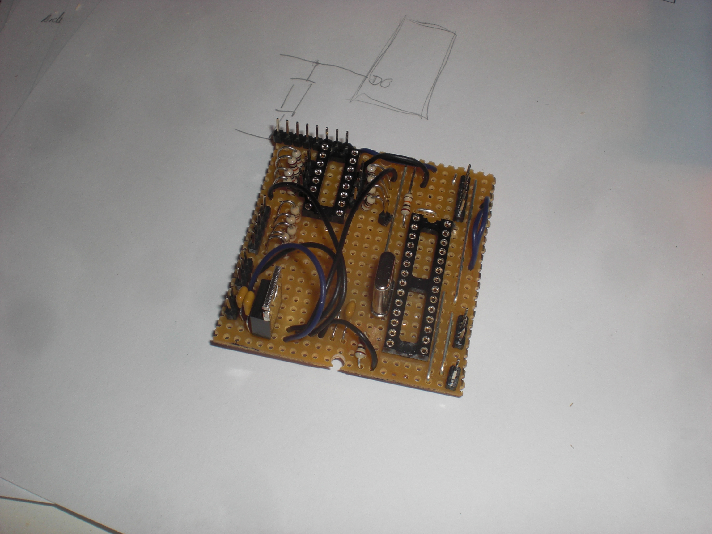
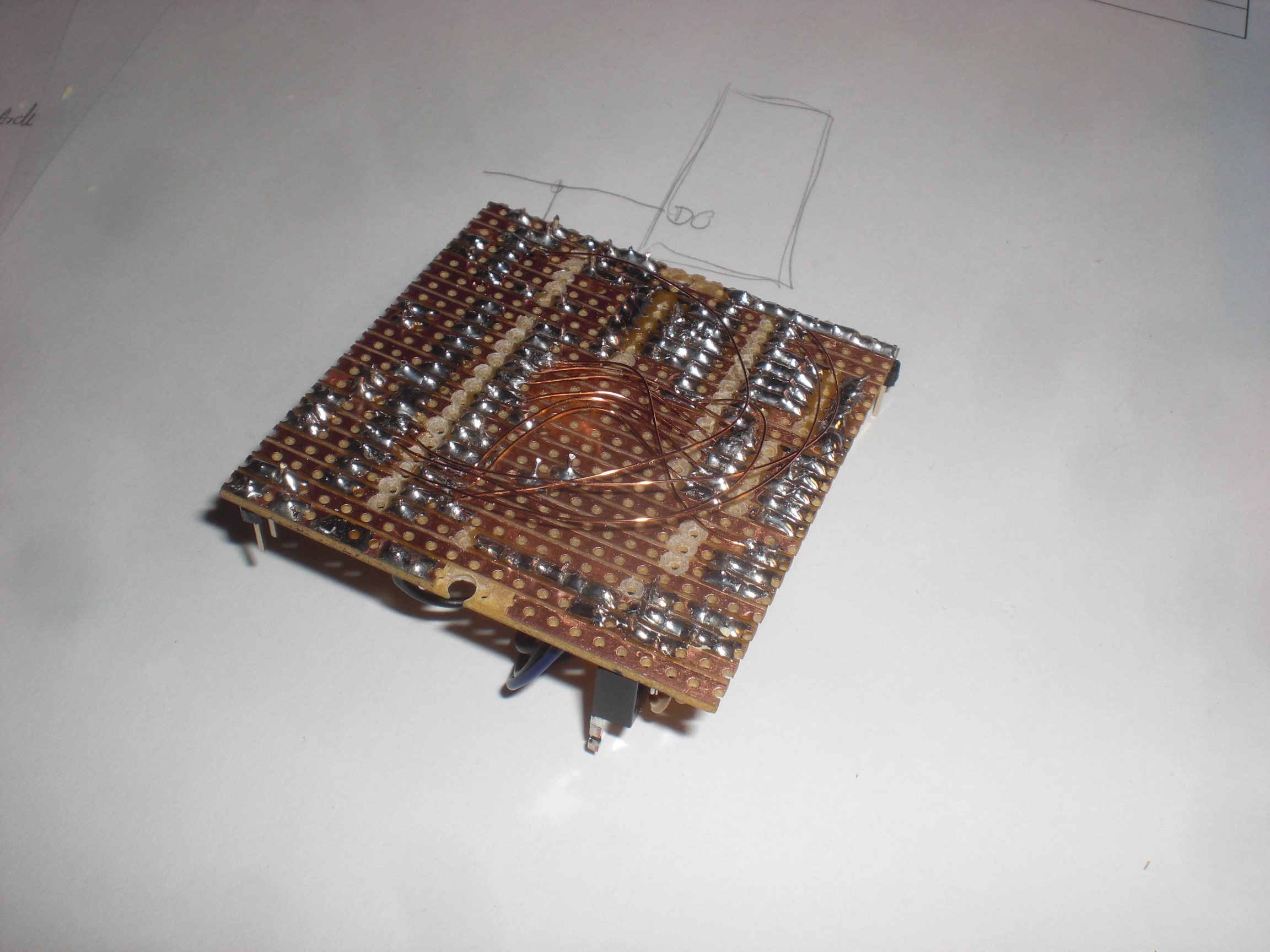
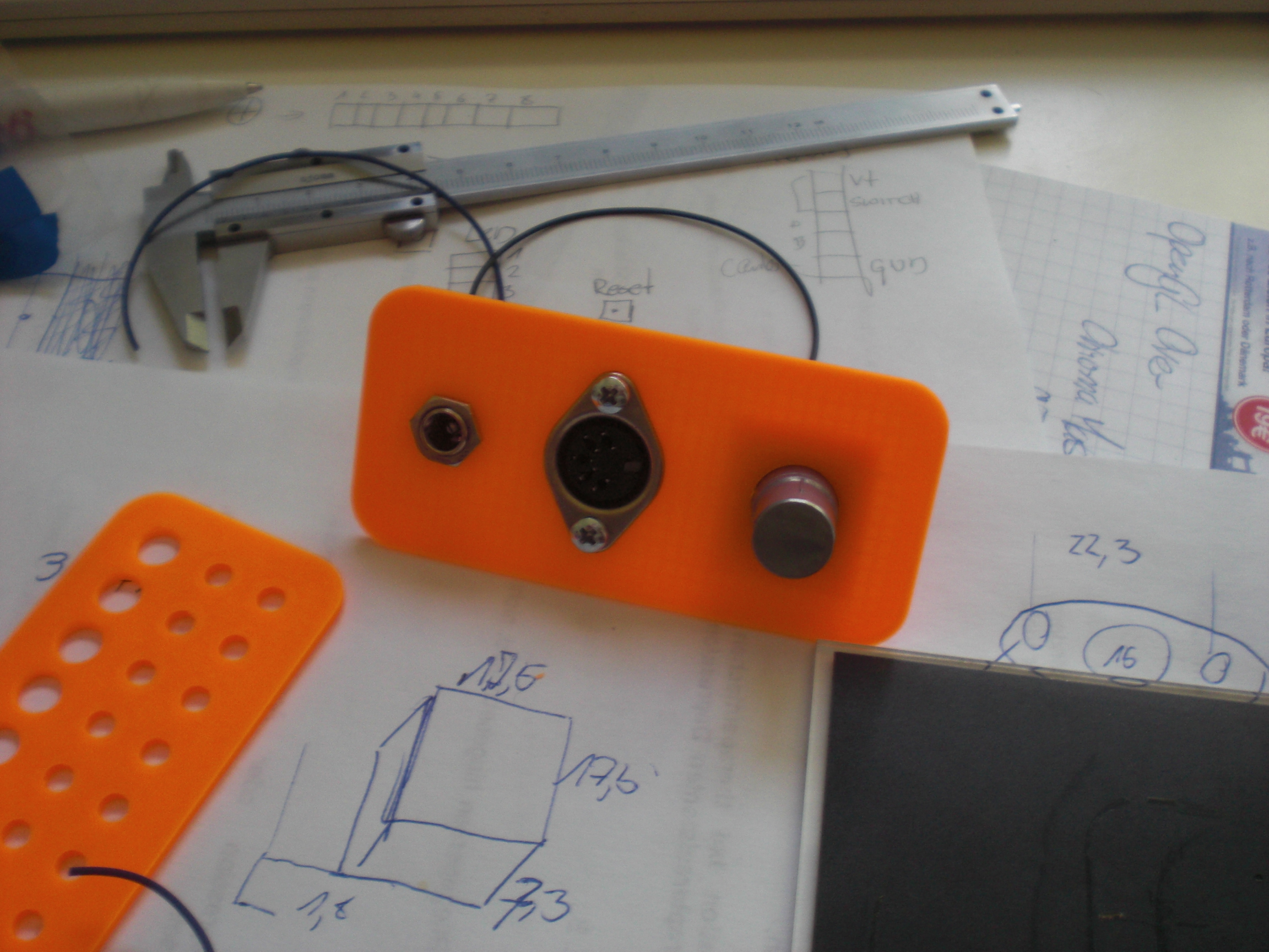
This project is the first one to benefit from my new 3D Printer. Due to the fact that I don’t have a dedicated toolshed anymore it’s kind of impossible to reliably manufacture the case anymore. Seems as if I don’t need one from now on.
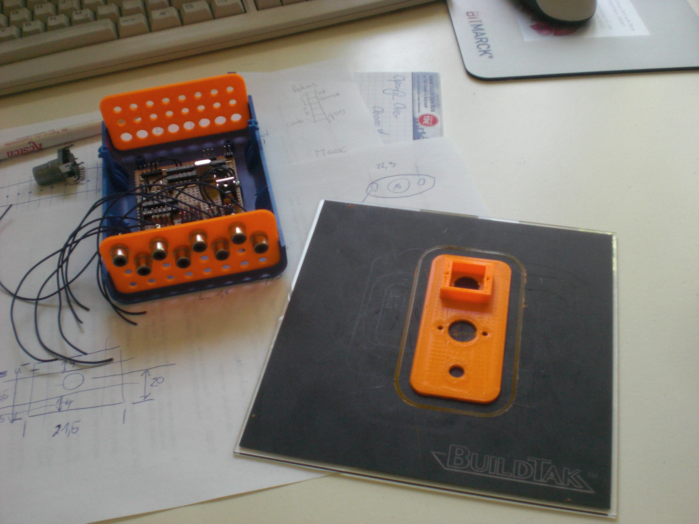
I really think the fixation of the rotary encoder is one of the smartest pieces ever done by mankind. Ever =)
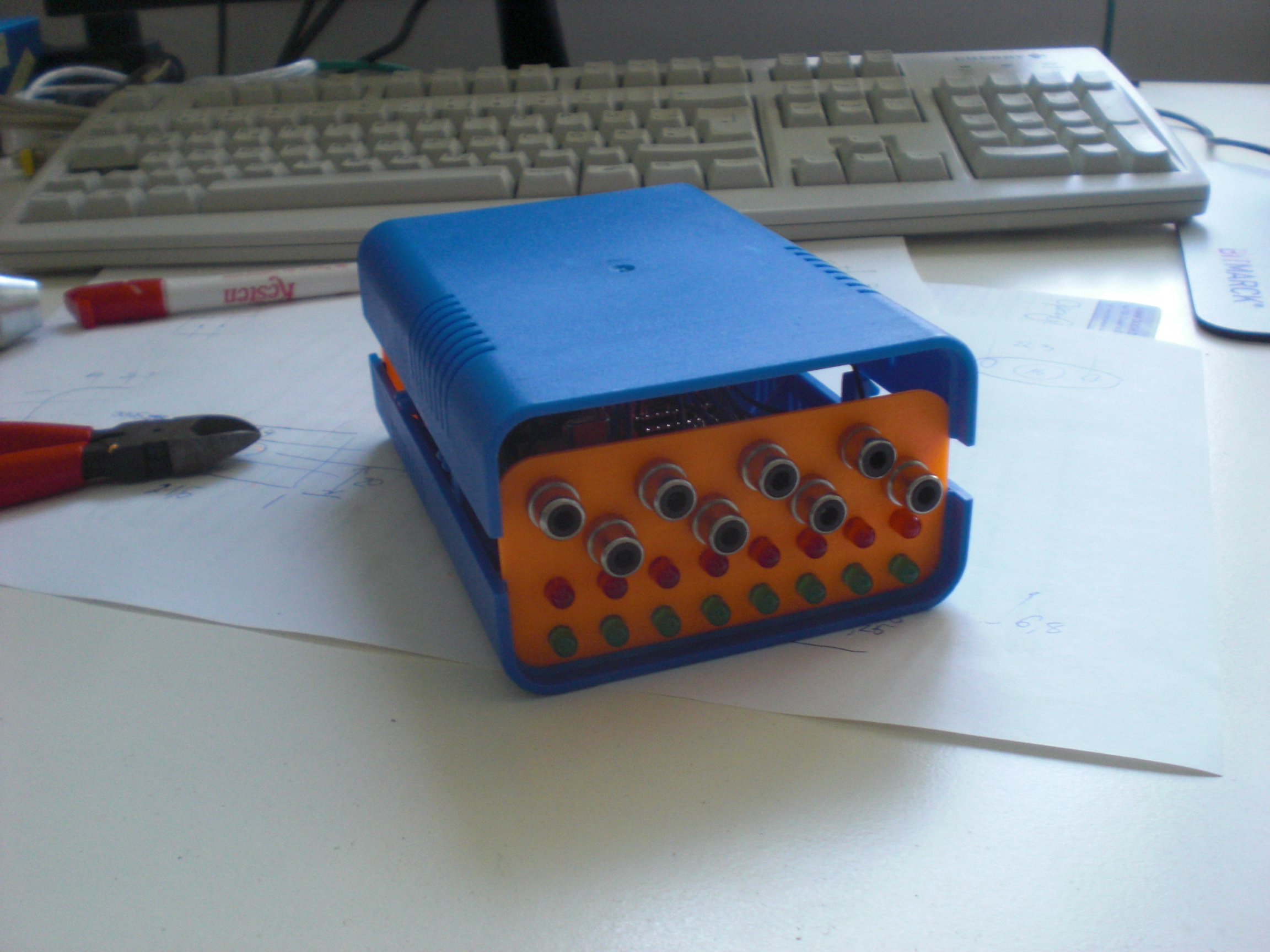
The LEDs are driven via Charlieplexing. It’s rather easy to implement but you really need to concentrate while soldering. By the way: If everything else fails I guess I’ll become a Soldering-Artist one day.

The function of the device is easy to explain. Every input is triggered when the state of a connected switch changes. This is indicated by the red LED below the channel. The green LEDs indicate the channel that’s influenced by the rotary enoder: The encoder gives the possibility to set the time that has to pass from the moment the input is triggered until it can be retriggered again. Something like a ‘Retrigger Threshold’. The value can be set to values between 0 and ~2 seconds. When the lower / upper limit of the value is reached the green LED flashes. Pressing the rotary encoder (it has a built-in switch) switches to the next input.
A triggered input sends a MIDI note.


Ostern 2015. Vorbereitung für die ProLight+Sound.
Überall ist Technik, überall liegt Arbeit

Welcome into my world. Eigentlich is’ es hier immer so.
Genau. Prolight+Sound 2015. Und genau DAS ist der Grund, warum hier in den letzten Jahren Monaten so gut wie gar nichts passiert ist.
Ich arbeite seit circa 7 Jahren an ~einem Projekt~. In den letzten 2 Jahren hat sich die ganze Sache nochmal konkretisiert und seit Dezember 2014 war klar, dass wir als Aussteller zur Prolight+Sound fahren. Seitdem gab es hier sowieso keine freie Minute mehr und meine gesamte freie Zeit ist in die Entwicklung des Produkts und die Vorbereitung der Messe geflossen.
Wer sich jetzt wundert, warum man 7 Jahre an einem Projekt sitzt und quasi 5 davon nicht richtig zu rande kommt, dem sei hier gesagt, dass das natürlich alles parallel zu meinem ‘echten’ Leben stattfindet. Dazu noch Ärger mit ehemaligen ‘Geschäftspartnern’ und ausserdem -und das ist kein Witz- waren wir vom groben Konzept schon 2008 so weit, wie heute; allein: Der Markt war fühlbar noch nicht bereit dafür. Nun isses aber soweit und wir müssen unser Kram den Leuten nicht mehr anbieten wie Sauerbier, sondern stoßen auf echtes Interesse.
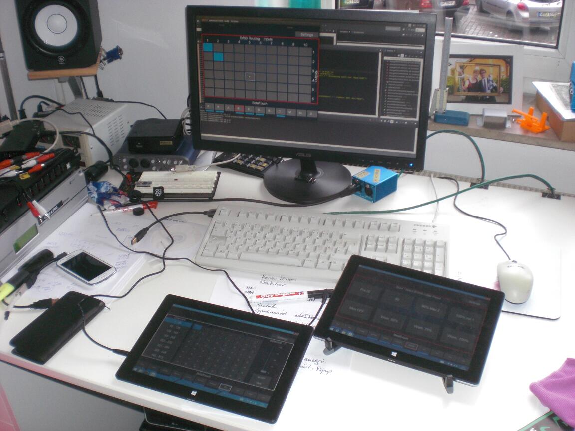
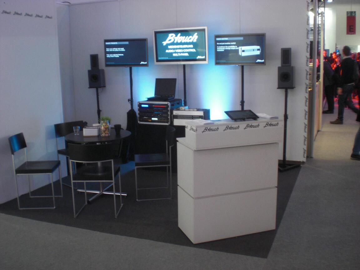
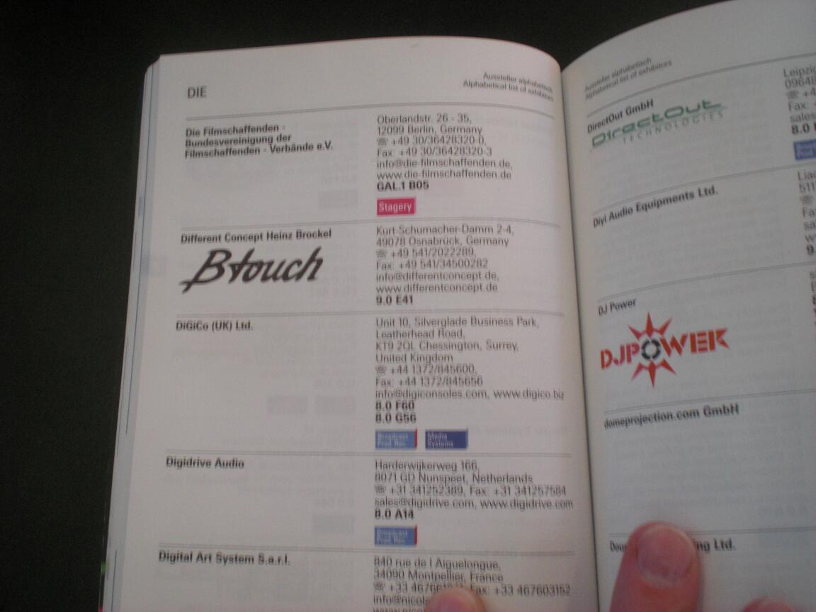
Nur kurz: Es handelt sich um eine Lösung, um AudioVideoLicht-Settings für Nicht-Techniker bedienbar zu machen (und so abzusichern, dass Dein Cocktailmixer-Ich-bin-auch-DJ-Kumpel nicht die Settings versauen kann). Natürlich mit einer Möglichkeit, das alles von mehreren Räumen aus zu erledigen, etc. Ganz nebenbei haben wir eine enorm geniale HDMI-Matrix am Start und alles passt so richtig gut zusammen. Das Thema wird hier erst einmal nicht weiter breitgetreten. Mehr Info dazu gibt es auf der offiziellen Seite: www.BetaTouch.de
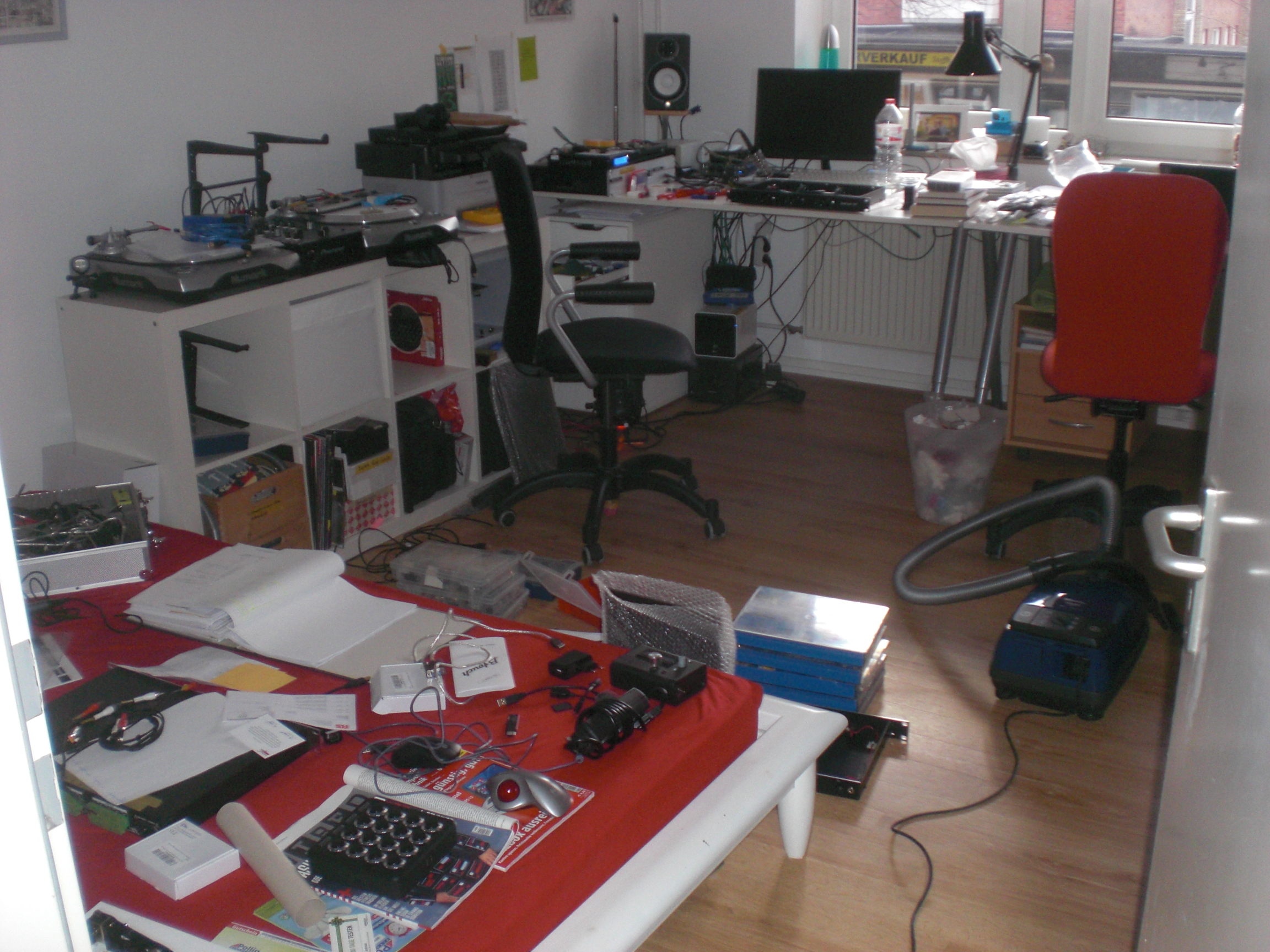
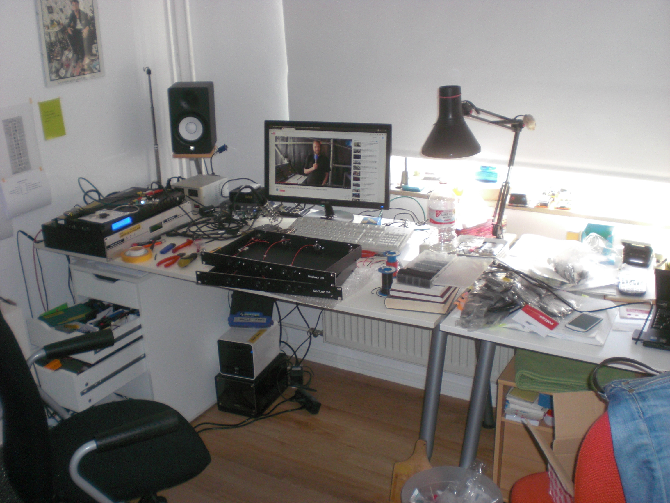
Egal. Die letzten 2 Jahre jedenfalls sah mein Schreibtisch bestenfalls so aus, sofern er aufgeräumt war:
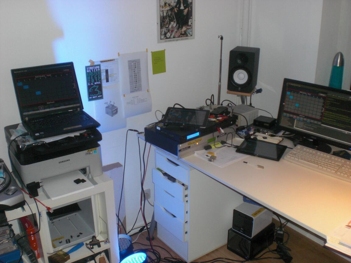
Immer (IM-MER) mindestens 3 Rechner gleichzeitig, ein Riesenhaufen Zettel mit wahllos verstreuten Notizen. Zusätzlich ein Haufen 19″ Geräte, die immer alle ausnahmslos angeschaltet sind, kilometerweise Kabel, Klebeband, Beschriftung, Lampen, ….
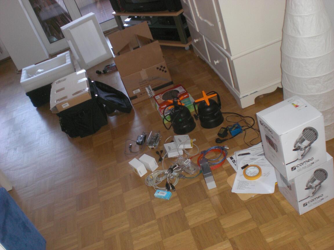
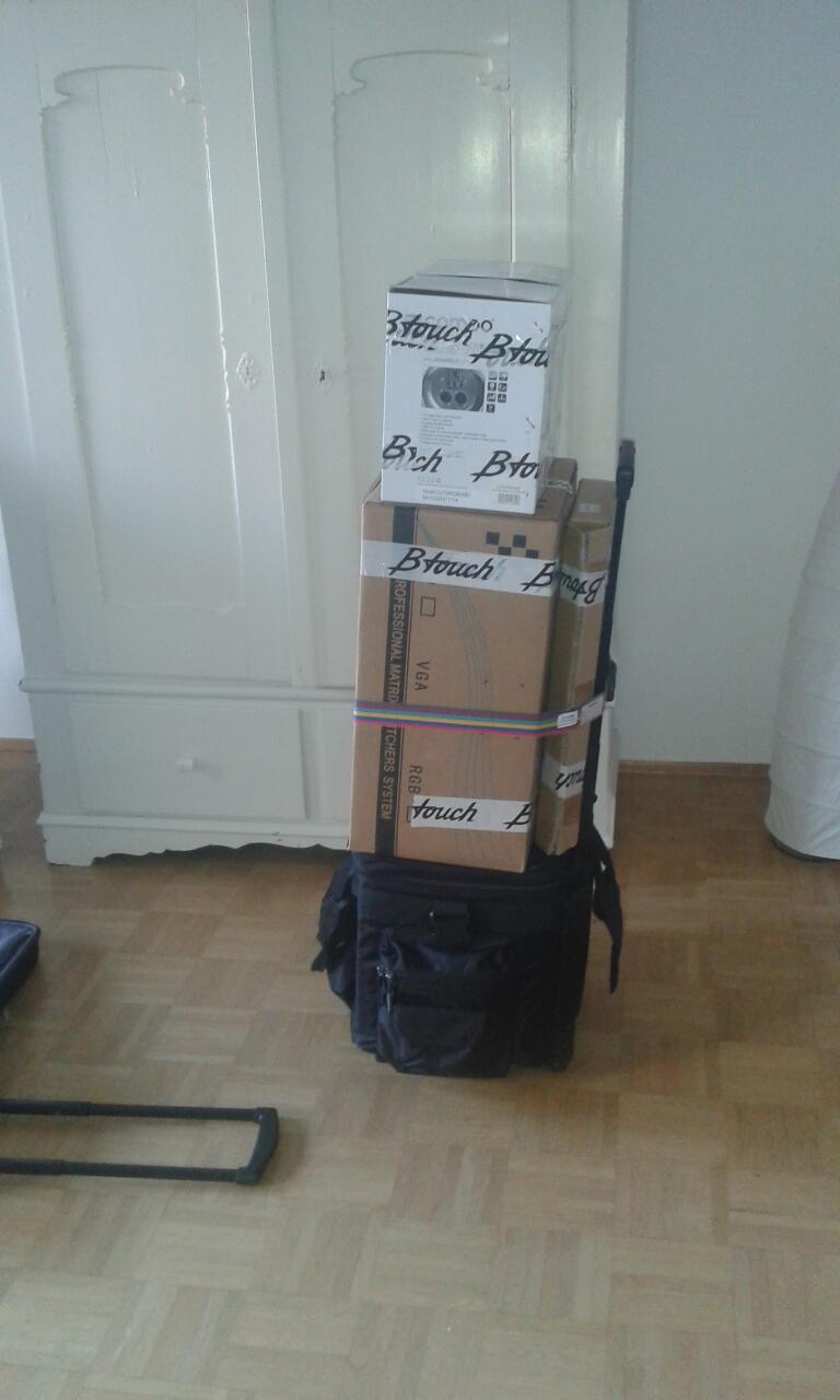
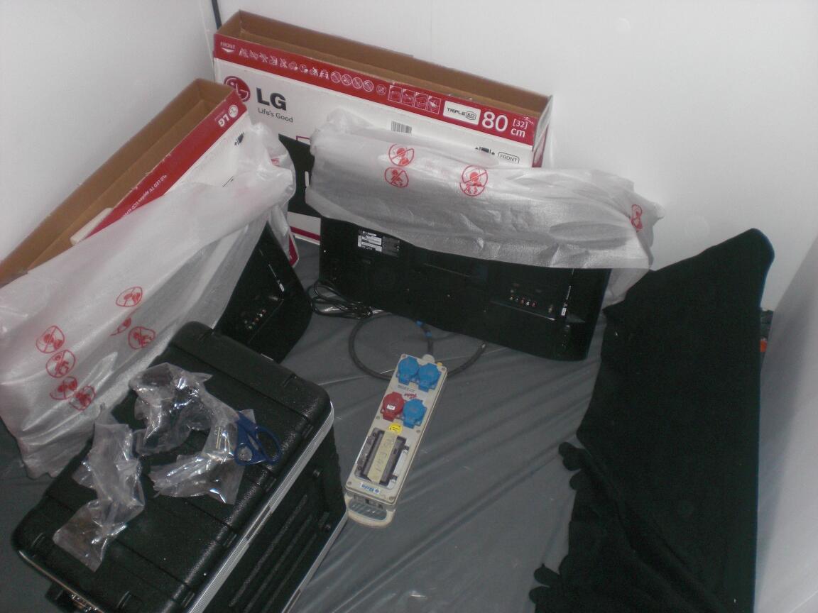
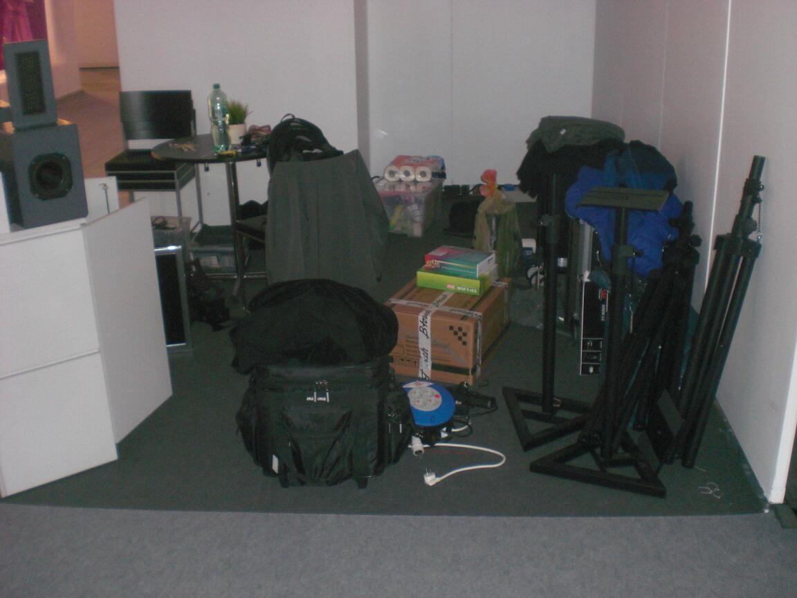
Der ganze Kram, den ich zur Messe nehmen musste: 4 Stück 19 Zoll Geräte (insgesamt 5HE), 2 Tablets, 2 LED PAR56, 2 Laptops, 1 USB Tastatur, 1 USB-auf-4-fach-seriell Wandler, Artnet-DMX Adapter, Netzwerkkabel, USB-Kabel, Zettel, CDs, Sticker, Netzteile, eine Steckdosenleiste, blahblahblah… und ein bisschen Wäsche für eine Woche, … Alles per Bahn.
Geht. Was noch fehlt ist der Trolley mit meiner Wäsche (und der Steckdosenleiste), aber es hätte schlimmer kommen können. Nicht sonderlich viel schlimmer, aber … etwas schlimmer.
Und schwupp-Di-Wupp war ich in Hamburg Frankfurt.

Anfangs sah das alles noch gar nicht so berauschend aus.
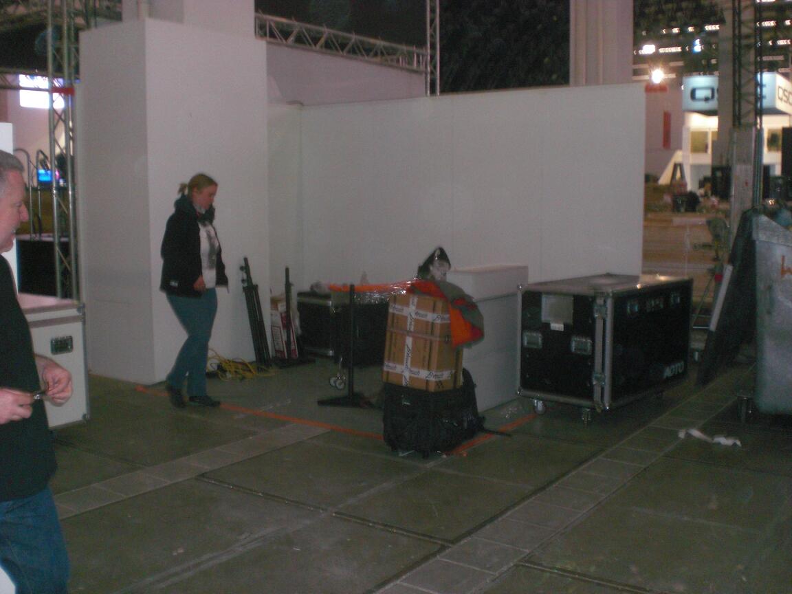
Aaaaber… das wurde noch. Um uns herum waren nur professionell gebaute Stände. Größer, bunter, mehr Zeug. Macht aber nichts. Wir haben es überhaupt nicht auf Laufpublikum und Kantenfummler abgesehen, sondern hatten unsere Termine und wollten einfach präsent sein, also alles cool.
Man macht sich anfangs echt keine Gedanken darum, wie viel Aufwand eigentlich hinter so einem Messestand steckt. Ist ja schließlich nicht nur so, dass man den Stand mitsamt dem eigentlichen Kram aufbauen muss, man muss ja auch passige Präsentationen, Videos, Flyer, Visitenkarten etc. haben. Alles muss 30tausend mal gegengelesen, korrigiert, übersetzt und nochmal korrigiert (und dann nochmal gegengelesen) werden. Nach dem Aufbau ist sowieso alles ganz anders und man muss nochmal ran. Schlau ist, sich nicht vom Messerummel (speziell dem Rummel nach offiziellem Ende des Messetages) unterpflügen zu lassen. Einfach mal nicht immer der letzte auf der Standparty sein….
Und weil wir alles richtig gemacht haben, waren wir entsprechend auffällig im Messeverzeichnis zu finden. Nüchtern betrachtet jetzt nicht soooo das Ding. Das gibt man an die PR Abteilung ab und… ach ja… wir haben keine PR-Abteilung.
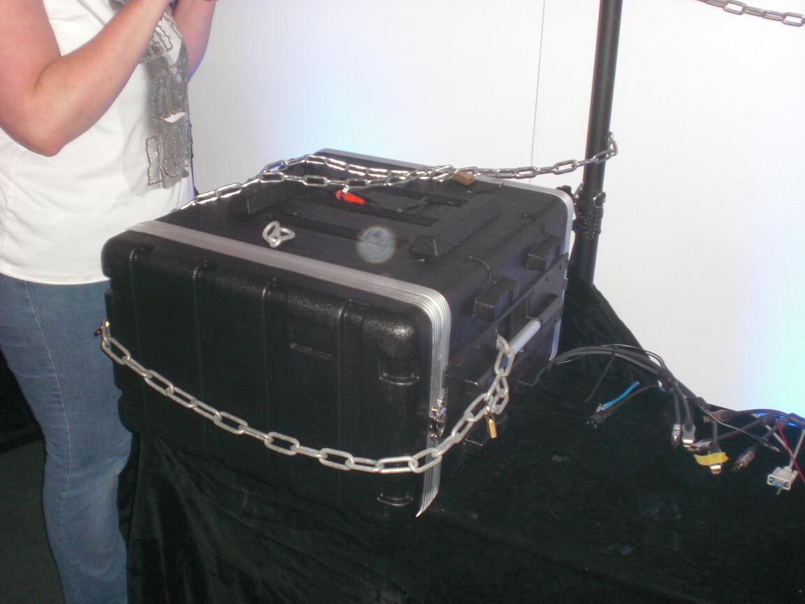
Abends den ganzen Schotter ordentlich anbinden. Man weiß ja nie. Es soll wohl Menschen geben, die mit einer klaren Definition von Eigentumsverhältnissen ihre Probleme haben.
Auch ein Vorteil von so einem kleinen Stand. Man benötigt eben keine 20 Stagehands, um das Ding innerhalb einer halben Stunde abzureißen. Flugs den alten Stand runtergeballert und in den Combi reingemöllert =) .
Fazit: Alles richtig gemacht. Alles.
Die beiden Anderen machen gerade die Nachbearbeitung (Kontakte anschreiben, Angebote zusammenstellen, Feedback koordinieren, etc).
Ich gönn’ mir jetzt erst mal eine Woche Nixtun. Also “nix” im Sinne von “nur den einen Hauptjob” und nebenbei ein bisschen Spaß-Programmierung: Es liegt noch ein angefangener Erschütterungssensor-To-Midi-Konverter bei mir herum, der wird jetzt fertiggemacht. Außerdem hab’ ich noch ein bisschen was von meinem Lieblingsbier zuhause.