
Latest Insta
Or: Creating an audio-signal with an Arduino, feeding it into a mixing desk, altering the frequencies via the mixer’s eq and analyzing the processed audio with another Arduino which then turns it into a MIDI-signal. Yes, that is Digital-to-Analog-to-Digital-to-Analog-to-Digital-conversion. Phew!
Here’s a picture of the setup:
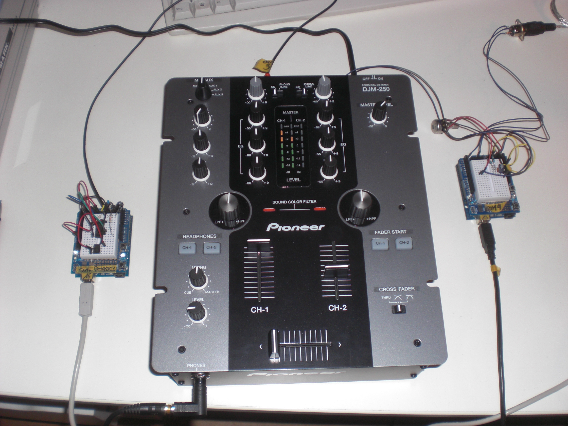
On the left side there is a circuit consisting of an Arduino and an Attiny85. The Arduino creates a low-frequency ( ‘bass’ ) sine-shaped tone which perfectly sits in the frequency range of the mixer’s bass-EQ. I did some testing here to find the perfect frequency. Testing means: Using Ableton Live to create a white noise, feed this into the mixer, feed the mixer’s output back into Ableton and use the Spectrum-tool to see which frequency gets most influenced by the bass-EQ (C2, that is).
Creating a somewhat true sine needs some effort since the Arduino’s analog outputs only do PWM which isn’t very useful when talking about low-frequency audio signals. PWM basically creates a square-wave signal with a certain pulse-pause relation. While this might be okay for dimming an LED, this becomes quite unusable when dealing with audio because you can simply hear that it’s no sine – the lower the frequency the more the signal turns into some sort of ‘click’-noise. No wonder, the bass-EQ doesn’t influence this to any convience.
That’s why I used this solution to make the Arduino spit out something that’s a little more sinewave-like. I ommitted the circuit as you may see on the picture below. I didn’t have the necessary parts lying around and it worked nevertheless.
The Attiny85 is used to create the second tone. It’s a simple PWM signal at 480 Hz. This time the PWM-nature of the signal can be used for our benefits: A square-wave signal has a recognizable amount of harmonics. You don’t hear one but (at least) two tones. Perfect for us because the mixer I used perfectly influences (well … “perfectly” ) the signals with its mid- and hi-EQs.
The code for the Attiny85 looks like this:
void setup(){
pinMode(3, OUTPUT);
}
void loop(){
buzz(3,480,100);
}
void buzz(int targetPin, long frequency, long length) {
long delayValue = 1000000/frequency/2; // calculate the delay value between transitions
long numCycles = frequency * length/ 1000; // calculate the number of cycles for proper timing
for (long i=0; i < numCycles; i++){ // for the calculated length of time…
digitalWrite(targetPin,HIGH); // write the buzzer pin high to push out the diaphram
delayMicroseconds(delayValue); // wait for the calculated delay value
digitalWrite(targetPin,LOW); // write the buzzer pin low to pull back the diaphram
delayMicroseconds(delayValue); // wait again or the calculated delay value
}
}
I guess I found it over here and adapted it to my needs.
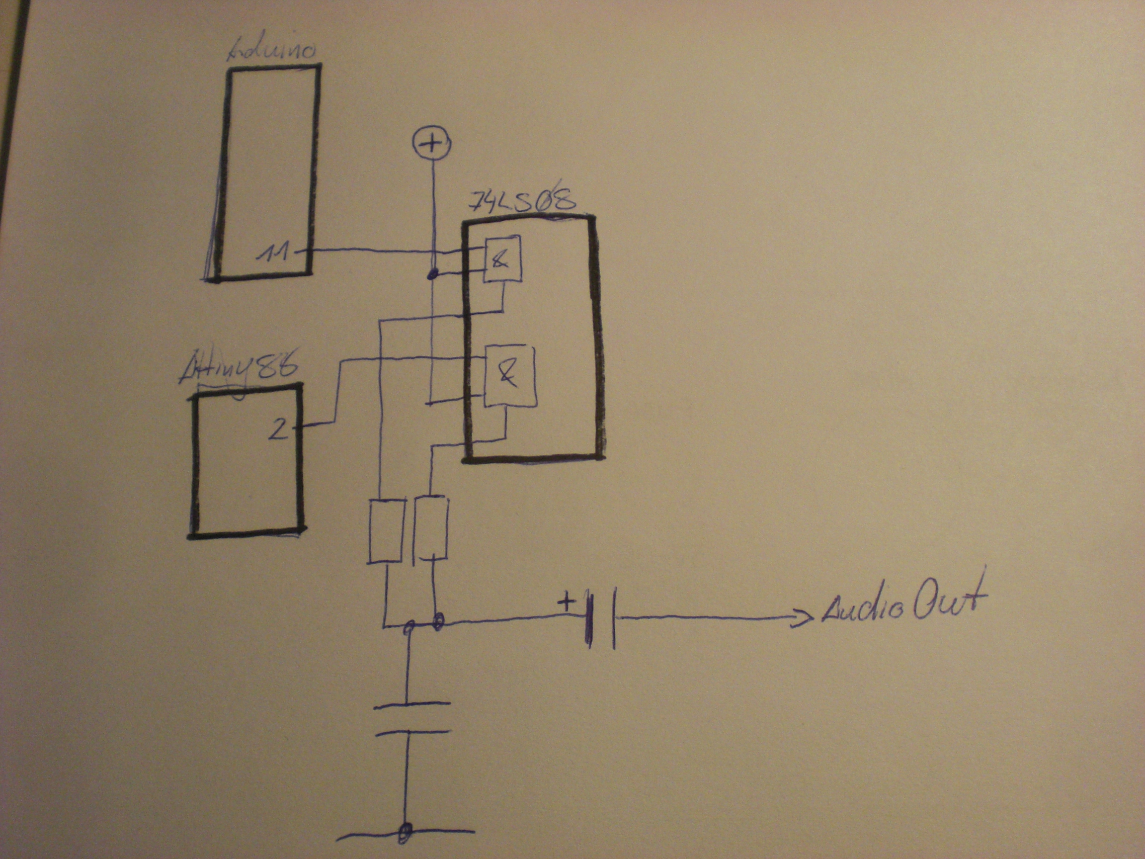
the two microcontroller’s output signals are fed into a 7408 (Quad AND) and then sent out into the analog world by a circuit I found over at the MunichMakerLab. This is my first audio-circuit with an Arduino. it’s probably spine-crawling for those who do this on a more professional base but I was getting the best results with this circuit.
[Edit] As someone pointed out in the comments section for this post on Hackaday this might read like I didn’t know at all what I am doing here or that it’s all just a big coincidence. This is not correct. The AND gate protects the audio sources from interfering with each other for a certain amount. I tested that, it simply sounds cleaner. At least I had a certain intention when I added the gates to the circuit (…not that I completely remember….). Looking at the circuit I am still wandering about _why_ but that’s one of the things that I file as ‘Audio things’ for now. [/Edit]
The signal is fed into the mixer and from the mixer sent to another Arduino which does the processing. the circuit looks like this:

To be honest: I cannot really remember where I got this circuit from. Somehow all the solutions I found while trying to find the circuit again look a little different. Again this might be spine.crawling for some of you but… it’s a fun project and it works. The code for the realtime audio-analysis is based on the FHT library by openmusiclabs and expands an example I found over at dontquityourdayjob.
/////////////////////////////////////////////////////////////////////
// Easy Customizations
/////////////////////////////////////////////////////////////////////
// Adjust the Treshold – what volume should make it light up?
#define THRESHOLD 40
// Attempt to ‘zero out’ noise when line in is ‘quiet’. You can change this to make some segments more sensitive.
int oct_bias[] = { 600, 600, 1, 100, 50, 50, 50, 50 };
// Divide Threshold by 2 for top octave? 1 – yes 2 – no. Makes highest frequency blink more.
#define TOP_OCTAVE_DIVIDE false
/////////////////////////////////////////////////////////////////////
// Hard Customizations – know what you are doing, please.
/////////////////////////////////////////////////////////////////////
// FHT defaults – don’t change without reading the Open Music Labs documentation at openmusiclabs.com
#define LOG_OUT 0 // use the log output function
#define FHT_N 256 // set to 256 point fht
#define OCTAVE 1
#define OCT_NORM 1
// Delay – defines how many cycles before the lights will update. OML’s algorithm at 256 samples (needed for our 8 octaves) takes
// 3.18 ms per cycle, so we essentially throw out 14 cycles (I used mechanical relays, you can lower this for solid state relays).
// 15 cycles = 47.7 ms update rate. Be careful here and don’t change it too quickly! I warned you!
#define DELAY 15
#include <FHT.h> // include the library
#include <MIDI.h>
void setup() {
Serial.begin(31250); // use the serial port
TIMSK0 = 0; // turn off timer0 for lower jitter
ADCSRA = 0xe5; // set the adc to free running mode
ADMUX = 0x40; // use adc0
DIDR0 = 0x01; // turn off the digital input for adc0
}
/**********************************************************************************
Loop – includes initialization function and the full loop
**********************************************************************************/
const int NUMREADINGS=10;
int readings[NUMREADINGS]; // the readings from the analog input
int index = 0; // the index of the current reading
int total = 0; // the running total
int average = 0;
int bassVal;
int midVal;
int hiVal;
int bassValOld;
int midValOld;
int hiValOld;
const int OUTTHRESHHOLD = 4;
void loop() {
// True full loop
int q = 0;
while(1) { // reduces jitter
cli(); // UDRE interrupt slows this way down on arduino1.0
for (int i = 0 ; i < FHT_N ; i++) { // save 256 samples
while(!(ADCSRA & 0x10)); // wait for adc to be ready
ADCSRA = 0xf5; // restart adc
byte m = ADCL; // fetch adc data
byte j = ADCH;
int k = (j << 8) | m; // form into an int
k -= 0x0200; // form into a signed int
k <<= 6; // form into a 16b signed int
fht_input[i] = k; // put real data into bins
}
fht_window(); // window the data for better frequency response
fht_reorder(); // reorder the data before doing the fht
fht_run(); // process the data in the fht
fht_mag_octave(); // take the output of the fht
sei();
if (q % DELAY == 0) {
//—-Smoothing
// subtract the last reading:
total= total – readings[index];
// read from the sensor:
readings[index] = (fht_oct_out[1] – oct_bias[1]);
// add the reading to the total:
total= total + readings[index];
// advance to the next position in the array:
index = index + 1;
// if we’re at the end of the array…
if (index >= NUMREADINGS)
// …wrap around to the beginning:
index = 0;
// calculate the average:
average = total / NUMREADINGS;
//—-
//Werte:
bassVal = average; // : Bass
midVal = fht_oct_out[4] – oct_bias[4]; // Mitte
hiVal = fht_oct_out[7] – oct_bias[7]; //Hochton
bassVal = map(bassVal, -450, -390, 0, 127);
midVal = map(midVal, 9, 107, 0, 127);
hiVal = map(hiVal, -34, 20, 0, 127);
if((bassVal > bassValOld+OUTTHRESHHOLD) || (bassVal < bassValOld-OUTTHRESHHOLD)){
if((bassVal>=0) && (bassVal<=127)){
Serial.write(0xb0);
Serial.write(0x01);
Serial.write(bassVal);
}
bassValOld = bassVal;
}
if((midVal > midValOld+OUTTHRESHHOLD) || (midVal < midValOld-OUTTHRESHHOLD)){
if((midVal>=0) && (midVal<=127)){
Serial.write(0xb0);
Serial.write(0x02);
Serial.write(midVal);
}
midValOld = midVal;
}
if((hiVal > hiValOld+OUTTHRESHHOLD) || (hiVal < hiValOld-OUTTHRESHHOLD)){
if((hiVal>=0) && (hiVal<=127)){
Serial.write(0xb0);
Serial.write(0x03);
Serial.write(hiVal);
}
hiValOld = hiVal;
}
}
++q;
}
}
The whole mechanism is not THAT precise but it gets the job done and it’s a fun thing to watch. The bass-frequency has to be smoothed-out quite a bit in order to make it all work. After spending a little more than a day with this some might ask “what for?”. I tell you what for: for the sake of finally doing it. I had this idea for over a year now and it was well worth trying.
The system is quite slow in its reaction (mainly caused by the necessary smoothing) and results are still a bit unpredictable but turning an audio-mixer into a midi-controller just by using hardware of ~10€ ain’t too bad, isn’t it?
[tube]https://www.youtube.com/watch?v=u5r6i65eHKk, 720, 540[/tube]
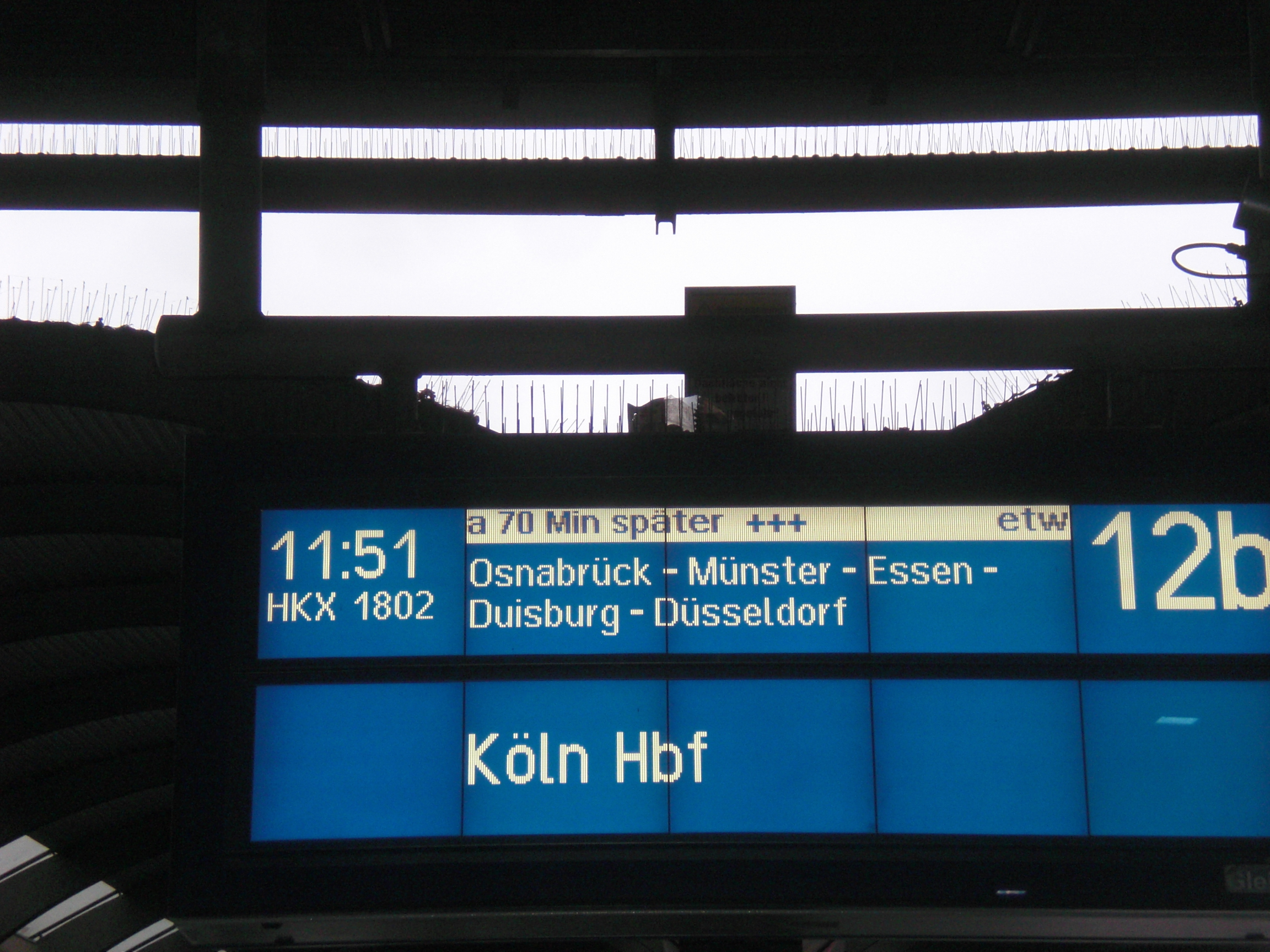
Due to various reasons (and only some of them are cool) I haven’t done a lot of jobs as a lightjockey within the last 2 years. But destiny seems to be on my side at the moment and so I had the chance to do the lights and visuals at the ‘Graudate’s Ball 2014’ in Osnabrück. the whole event was very professionally done so it was very much like an industrial event. Dates like these are mainly characterized by a rather fixed timetabel and a somewhat limited necessity for pure creativity and next-generation-visuals. It has to work and it has to work on time. That’s why you are there, that’s what you are paid for (mostly).
The event already started with a delay. I had to get from Hamburg to Osnabrück and was more than an hour late even before anything happened at all. Fortunately I knew about the fact that most things were already set up at the venue. This was one of those jobs I’d like to describe as a ‘Kofferjob’. Get there, get out your Laptop and voila! No need for building up an entire stage structure, cabling etc.
Mannmannmann, der erste Post seit über einem halben Jahr. Kann man nichts ändern, die Praxis Dr. Andy hat einfach alle Termine belegt =). Nun gut.
Ich entwickle gerade eine Software, die unter anderem per OSC mit der Aussenwelt kommunizieren soll. Nicht nur deswegen habe ich mich in letzter Zeit verstärkt mit dem Thema auseinander gesetzt und bin natürlich auf TouchOsc gestoßen, keine Frage. Ein ausgemustertes Smartphone hatte ich noch herumliegen, also flugs die App installiert und Feuer frei. Nach 1 Sekunde merkt man aber, dass es überhaupt keinen Spass macht, wenn das Smartphone mit TouchOsc dann beim herumspielen immer irgendwo herumliegt. Da ich kein Auto besitze und noch nie einen Halter für ein Smartphone besessen habe, musste ich schnell einen bauen (wenn, dann muss das alles auch ganzganzschnellunbedingtJETZT passieren, sonst geht das nicht. Klar, oder)?
Beim Stöbern durch mein Lager ist mir dieser Kabelhaken ins Auge gesprungen. Ich hatte mal einen ganzen Satz davon als eine Art Kabelrinne unter meinem Schreibtisch geschraubt. Die Aussparung zum Anschrauben passte dann auch ganz hervorragend in die Schraube vom Clip meines Gorillapods:

Was mir dabei auch aufgefallen ist: meine Kamera hat ihre besten Zeiten nun definitiv hinter sich. Dazu später aber irgendwann mehr. Dank Dremel und Tonnen von Heißkleber (vorsichtig und mit Schwung appliziert an ein Schutzgehäuse – nicht an das Handy selbst) wurde daraus dann auch in allerkürzester Zeit ein halbwegs brauchbarer Smartphone-Halter:
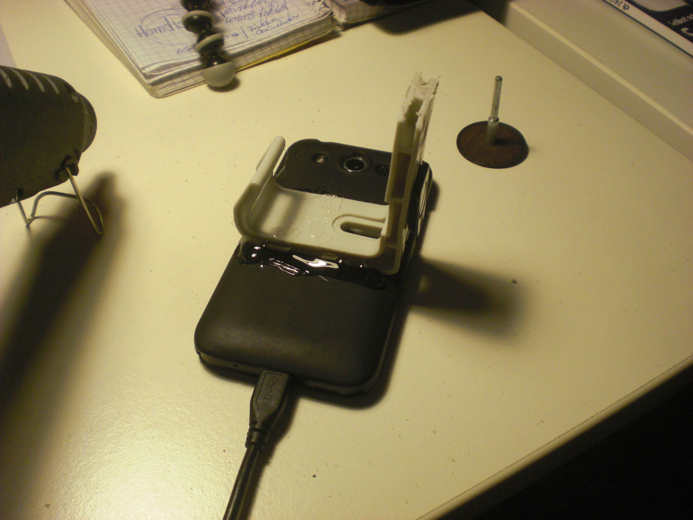

Fazit: Absolut perfekt. Ab-so-lut perfekt.
Momentan passiert hier mal wieder nicht so ultra viel. Das wird bald hoffentlich wieder. Ich arbeite gerade an ungefähr 800 Sachen gleichzeitig. Nunja.
Zwischendurch hab’ ich es aber immerhin geschafft, nach Frankfurt zur Pro Light & Sound zu fahren. Ist einiges von hängengeblieben. Aber das hier ist die Essenz des ganzen. Die Bieruhr steht auf 11.

I don’t know why I have never encountered this problem before but recently I tried to use my Traktor Audio 6 together with Ableton and had a fair share of problems. Basically I couldn’t route Ableton’s output to anything different then ‘Output 1&2’ which is the main output at the Audio 6’s front side. Everything else could be selected but just didn’t take effect (Ableton wasn’t even showing any kind of levels).
Same problem on the inputs: I have two turntables attached to the Audio 6 and wanted to use their inputs within a vst-plugin (MsPinky, as you may have guessed) but I just wasn’t able to get any signals coming into Ableton.
Of course the settings in Ableton all were correct. The screenshot only shows the output config but the input settings were accordingly.
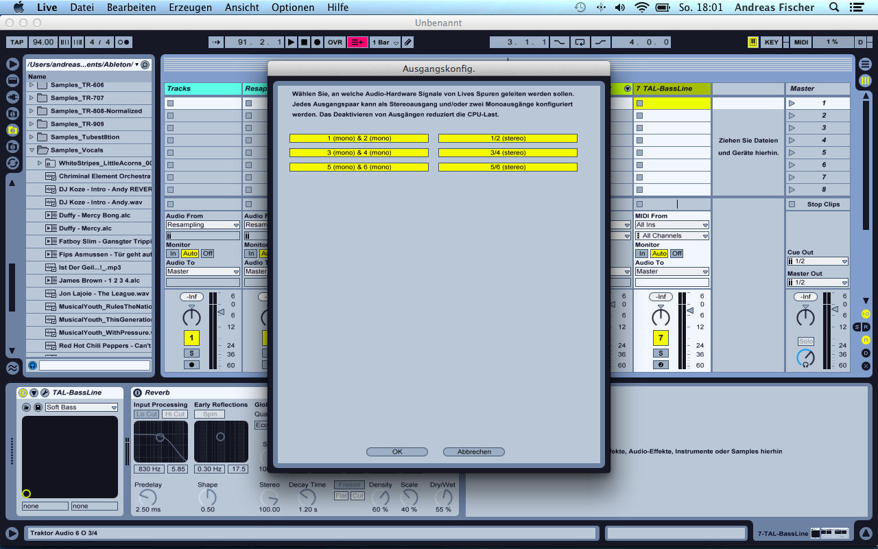
I had a simple clip running on a track and changed the Master Out settings a few times. Whatever I tried it only sent out real music (into my mixing desk) when I selected channel ‘1/2’ for Master out. 3/4 and 5/6 just kept being numb.
The problem behind all this is that the Audio device’s input settings for both channels 3/4 and 5/6 was set to ‘direct thru’. Meaning: Everything that is connected to the inputs is directly routed to the outputs. The device itself is not able to send audio data to these outputs in this case. Looking at it from a little distance it’s something I could have known before because every time I had Traktor Scratch running and attached the Audio 6 to my computer I was presented with a ‘direct thru’-configuration for both decks. I had to deactivate this every time I used it.
The solution is simple: Just open up the Audio 6 Control Panel and deactivate the checkbox for ‘direct thru’-mode. It’s probably a good idea to do this in the ‘startup’ tab since this changes the device’s configuration to behave like this automatically every time you connect it to your computer.
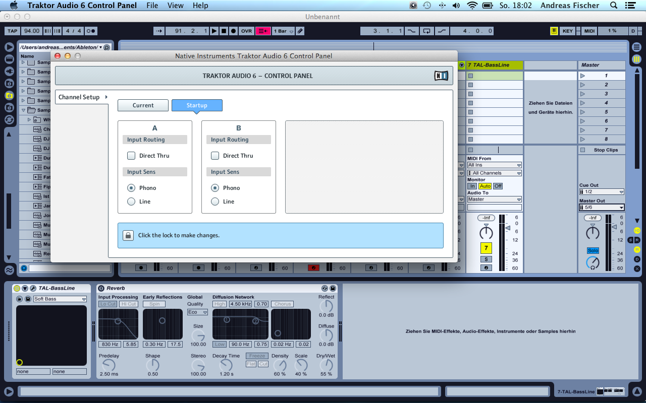
I don’t know if it’s necessary to do a reboot afterwards. While trying to find this solution I made so many of them I don’t know for sure.
Anyways: After making these steps I was able to select every possible input and output combination for my Audio 6 in Ableton – and all of them worked like a charm.
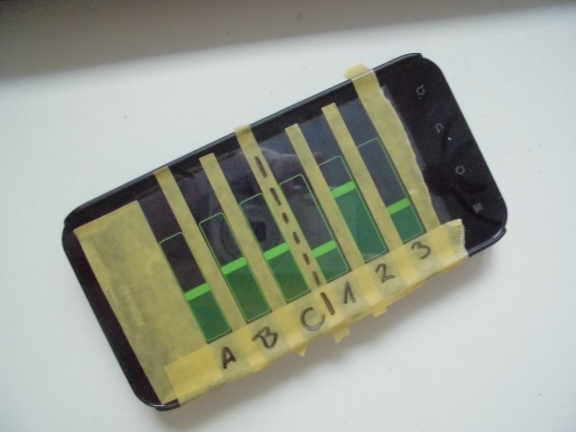
Using touchscreens for controlling other software (using TouchOSC, for example) one thing I always had my problems with was a missing tactile feedback. Using a hardware Midi-controller, for example, you don’t really have to look at it that much. many things just work because your fingers will find their way over the buttons to the correct knob.
This might not be the most sensible thing to do with a smartphone but… It helps. Once you find the correct slot your finger is automagically guided.
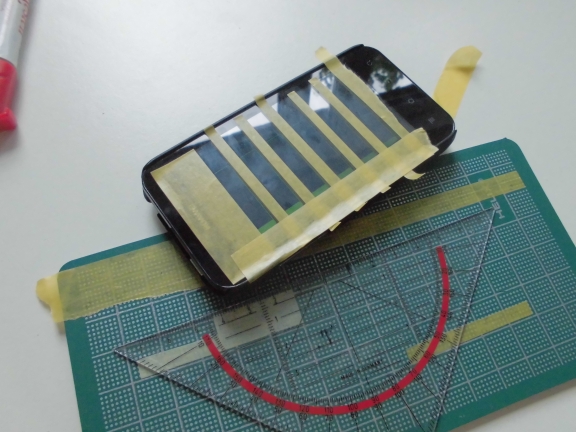
There are so many reasons why this is not the most sensible solution of all times but with the correct layout, proper spacing and some …
It just feels right. In the true sense of the word. Try it.
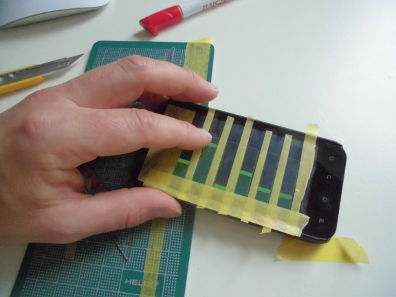
And you can take a marker to write on your smartphone. I like writing stuff on things.