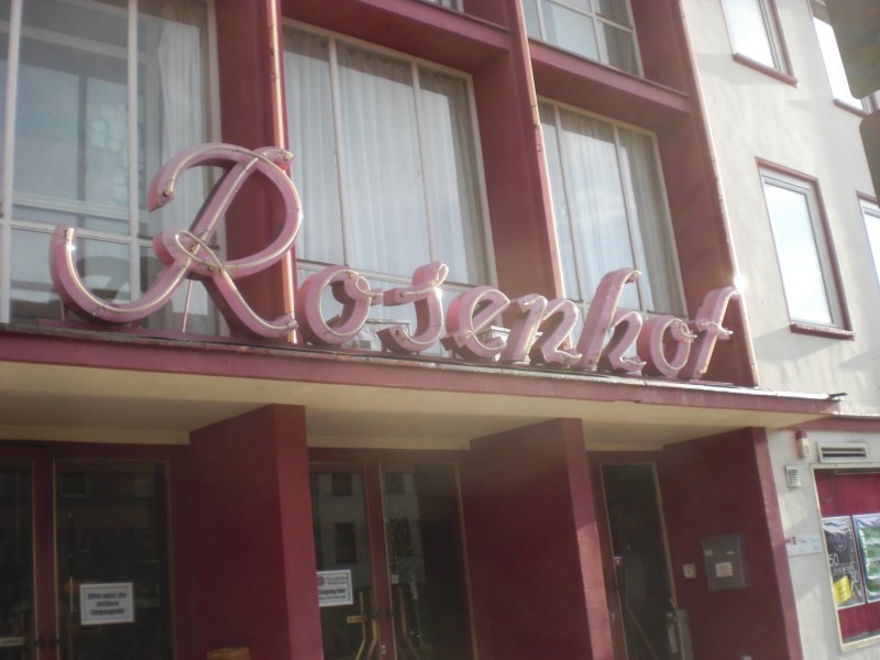
Ganz großartige Nummer. Seit geraumer Zeit habe ich hin und wieder einen Visual-Gig im Rosenhof Osnabrück. Bevor ich nach Hamburg gezogen bin, habe ich 10 Jahre in direkter Nachbarschaft gewohnt. 1986 mein erster Kinobesuch (damals war’s noch … ein Kino): “Didi auf vollen Touren”. Mit Mama. Klar, dass ich erst 250km wegziehen muss, damit sich was ergibt. Meine Bookings sind eben antizyklisch. Isso.
Es HAT einen auf eine gewisse Art und Weise kruden Charme. Is’ aber egal. Der Vibe stimmt. So richtig.
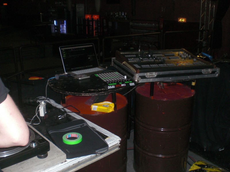
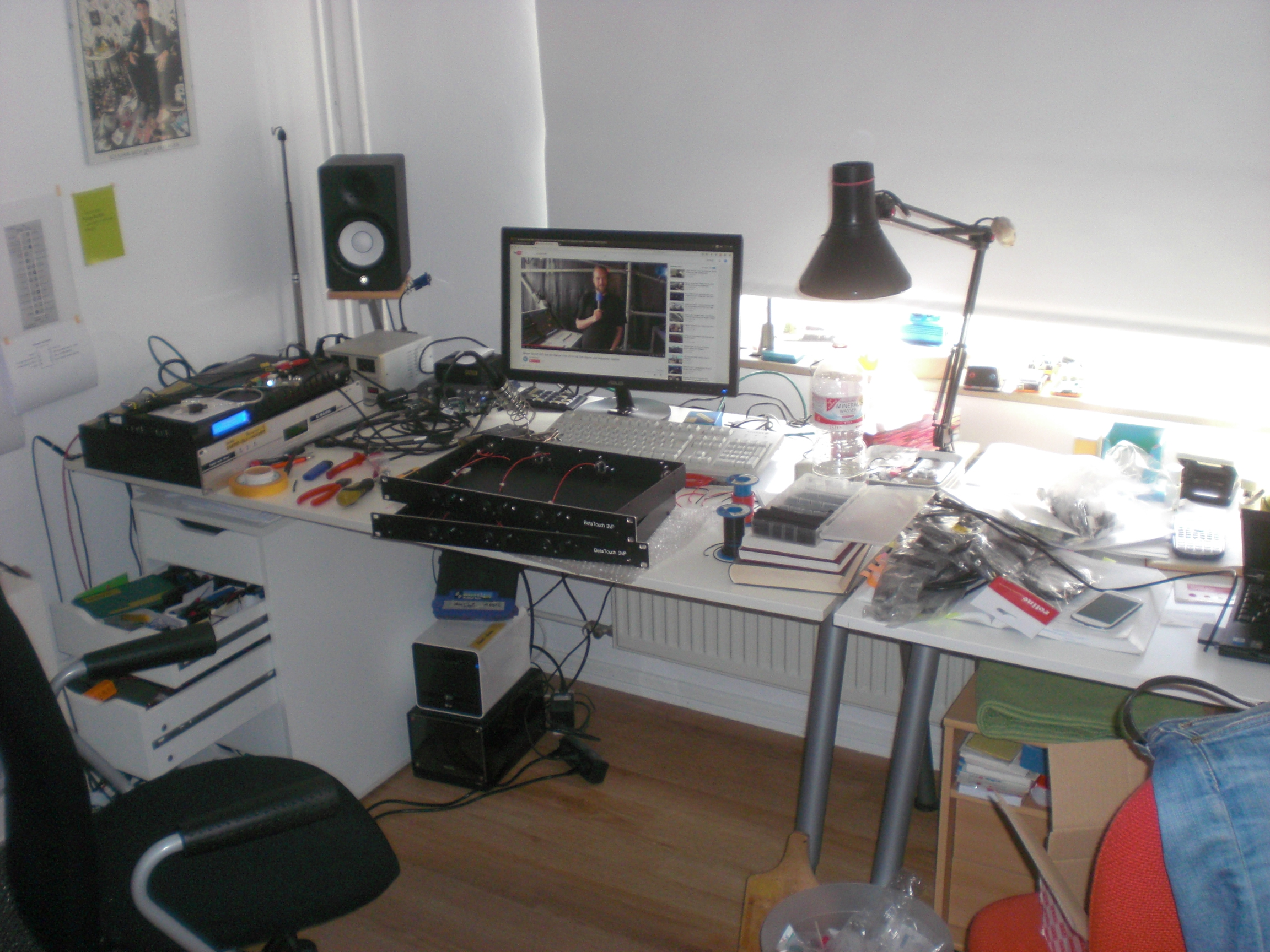
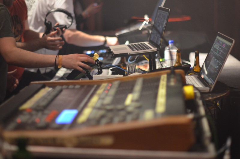
Am Pult sind wir in der glücklichen Lage, uns so richtig austoben zu können. LightCommander für’s Licht ist jetzt nicht das aktuellste Pult, verrichtet aber anstandslos seinen Dienst. Ich war kürzlich zu Besuch bei den Leuten von MA-Lighting und kann guten Gewissens behaupten, dass das hier nichts ist, wofür man sich schämen muss. =) Die zwei MacBooks für die Visuals hingegen sind absolut (ab-so-luHut) notwendig. Ich benutze VDMX und gehe per SyphonTCP in den Rechner des Haustechnikers, der die Visuals per Resolume konstruiert. So haben wir beide was davon, Er hat das letzte Wort und ich kann als Externer auch früher abbauen, um z.B. den ersten Zug zurück nach Hamburg zu kriegen (zu den Eindrücken einer vermeintlich ungestörten Zugfahrt Sonntag morgens um kurz vor fünf schreibe ich dann demnächst mal etwas).
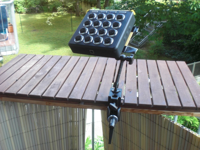
Mein aktuelles Set kann komplett per Midifighter gesteuert werden. Mit den Wiimotes wollte ich noch ganz viele lustige Sachen machen, die APC20 steuert Resolume auf dem anderen Rechner. Über das IPad wird eine GoPro ferngesteuert, die ~irgendwo~ versteckt ist.
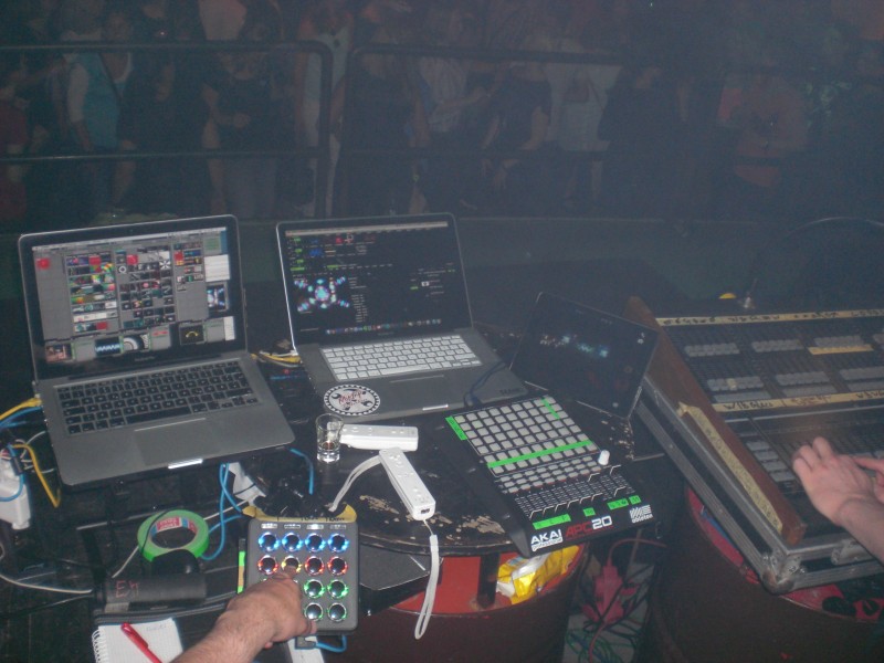
2 Leute für Licht und Visuals, 2 Leute für die Musik: 4 Rechner.
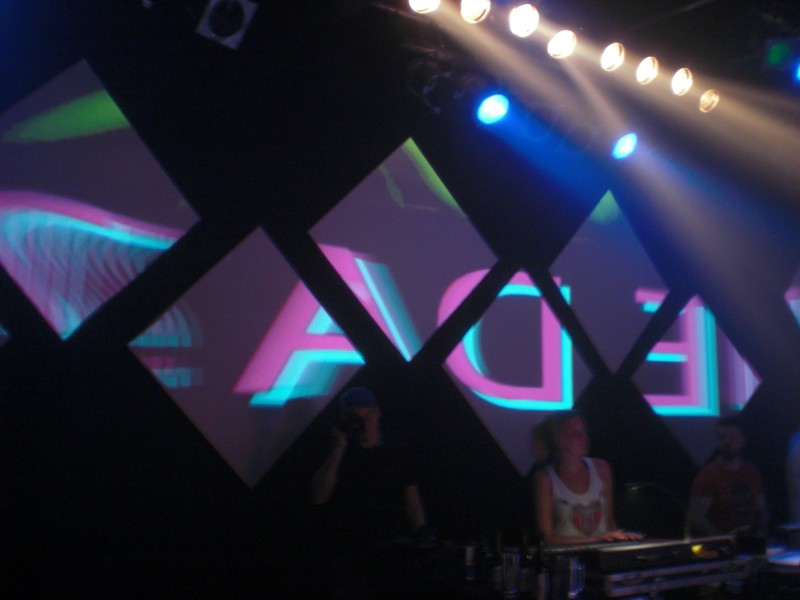
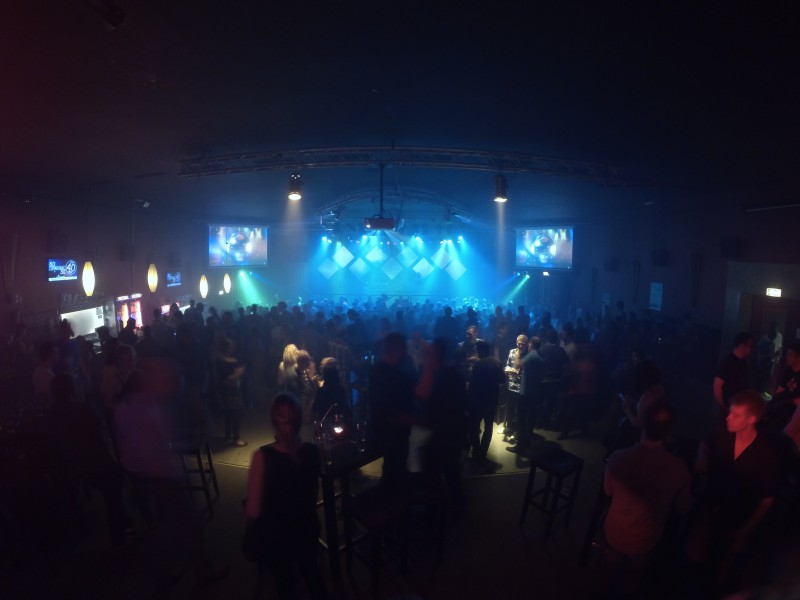
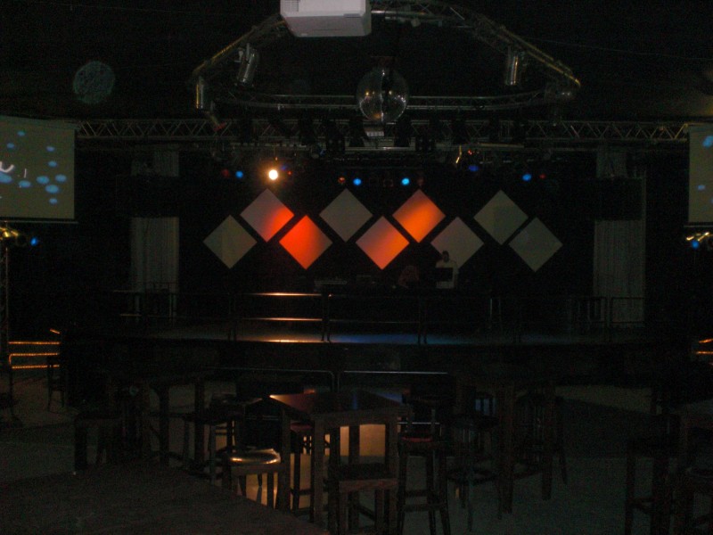
Und hier sehen wir Osnabrücks derzeit geilstes Video-Setup (Juni 2015). Ich bin technisch nicht ganz unschuldig daran (“3 Beamer steuert man am besten soundso”), aber Dominic vom Rosenhof tobt sich hier gerade richtig aus. Ehre, wem Ehre gebührt.
9 Panels im Backdrop dezent angestrahlt per Par64-Orange. Schlimmer geht eigentlich nicht, aber selbst das hat schon die ersten positiven Kommentare erzeugt. Links und rechts normale Leinwände. So haben wir es gelassen, bis angenehm viele Gäste da waren.
Dann Licht aus, alles dunkel, passende Musik und … Feuer frei. Hach, wie fein.
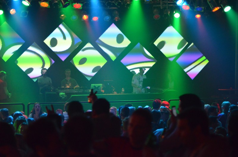
(Bitte im Hinterkopf behalten: 90er Party. Die Visuals sind also absolut auf den Punkt….)
Für Leute, die sich mit Visuals auskennen, ist das Mapping auf 9 Panels jetzt nicht das allerallerkomplizierteste auf der ganzen Welt, aber es haut einen trotzdem um. Weil es obergeil ist. Und streng genommen ist es auch für Leute, DIE sich mit Visuals auskennen, gar nicht so trivial. Mach’ das mal ohne Madmapper. Und dann bitte so, dass man die Deckkraft jedes Panels einzeln Regeln kann. Und alles mit Footage, deren Auflösung größer ist als 640*480. Und alles ohne Ruckler.
Vermeintliche Profis werden jetzt anmerken, dass es im Vidvox-Forum einen 12-Quad-ISF-Effekt gibt, der genau das ermöglicht. Genau. Dann rate mal, wer den programmiert hat.