Ostern 2015. Vorbereitung für die ProLight+Sound.
Überall ist Technik, überall liegt Arbeit
Welcome into my world. Eigentlich is’ es hier immer so.
Genau. Prolight+Sound 2015. Und genau DAS ist der Grund, warum hier in den letzten Jahren Monaten so gut wie gar nichts passiert ist.
Ich arbeite seit circa 7 Jahren an ~einem Projekt~. In den letzten 2 Jahren hat sich die ganze Sache nochmal konkretisiert und seit Dezember 2014 war klar, dass wir als Aussteller zur Prolight+Sound fahren. Seitdem gab es hier sowieso keine freie Minute mehr und meine gesamte freie Zeit ist in die Entwicklung des Produkts und die Vorbereitung der Messe geflossen.
Wer sich jetzt wundert, warum man 7 Jahre an einem Projekt sitzt und quasi 5 davon nicht richtig zu rande kommt, dem sei hier gesagt, dass das natürlich alles parallel zu meinem ‘echten’ Leben stattfindet. Dazu noch Ärger mit ehemaligen ‘Geschäftspartnern’ und ausserdem -und das ist kein Witz- waren wir vom groben Konzept schon 2008 so weit, wie heute; allein: Der Markt war fühlbar noch nicht bereit dafür. Nun isses aber soweit und wir müssen unser Kram den Leuten nicht mehr anbieten wie Sauerbier, sondern stoßen auf echtes Interesse.
Nur kurz: Es handelt sich um eine Lösung, um AudioVideoLicht-Settings für Nicht-Techniker bedienbar zu machen (und so abzusichern, dass Dein Cocktailmixer-Ich-bin-auch-DJ-Kumpel nicht die Settings versauen kann). Natürlich mit einer Möglichkeit, das alles von mehreren Räumen aus zu erledigen, etc. Ganz nebenbei haben wir eine enorm geniale HDMI-Matrix am Start und alles passt so richtig gut zusammen. Das Thema wird hier erst einmal nicht weiter breitgetreten. Mehr Info dazu gibt es auf der offiziellen Seite: www.BetaTouch.de
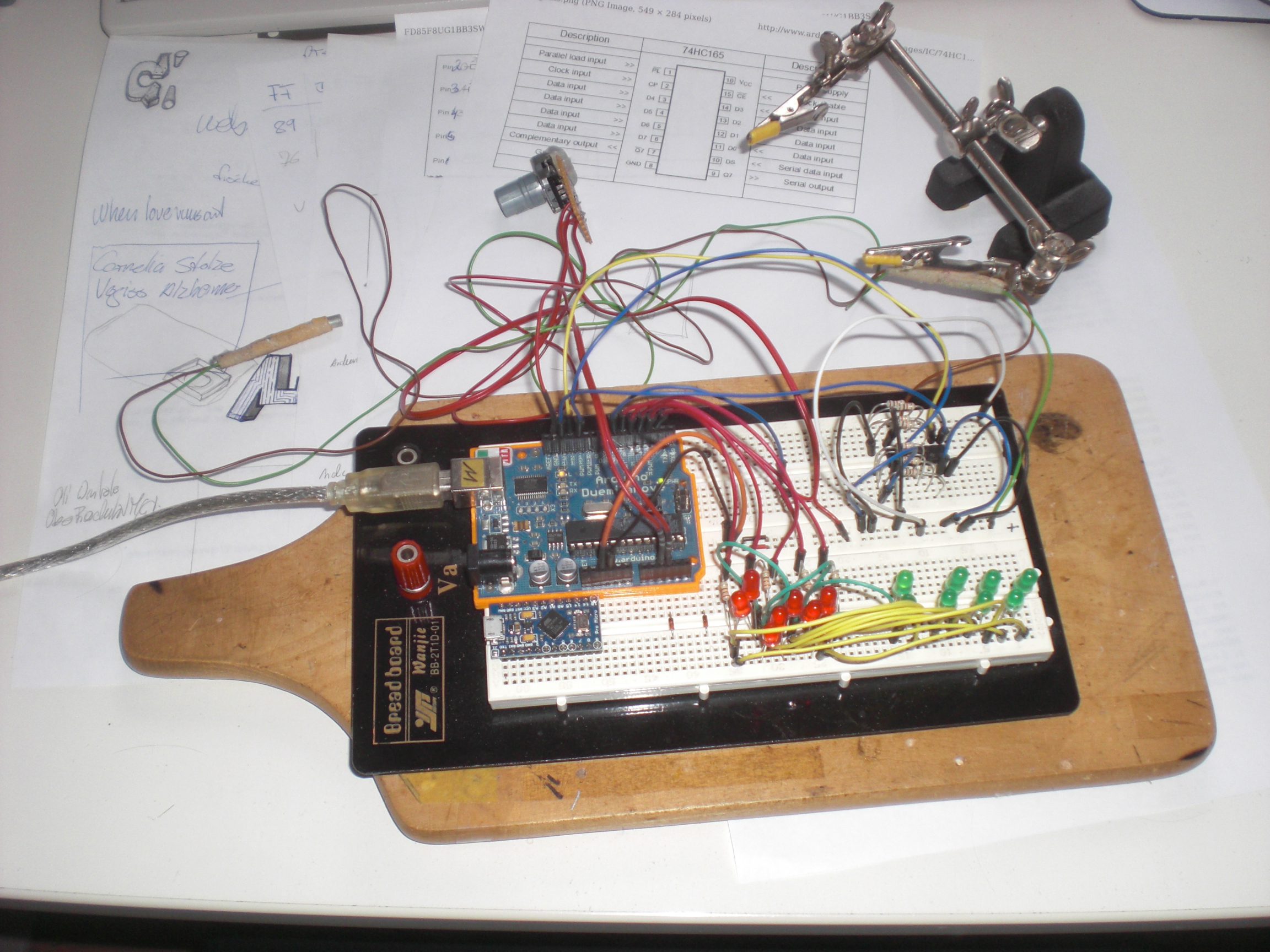
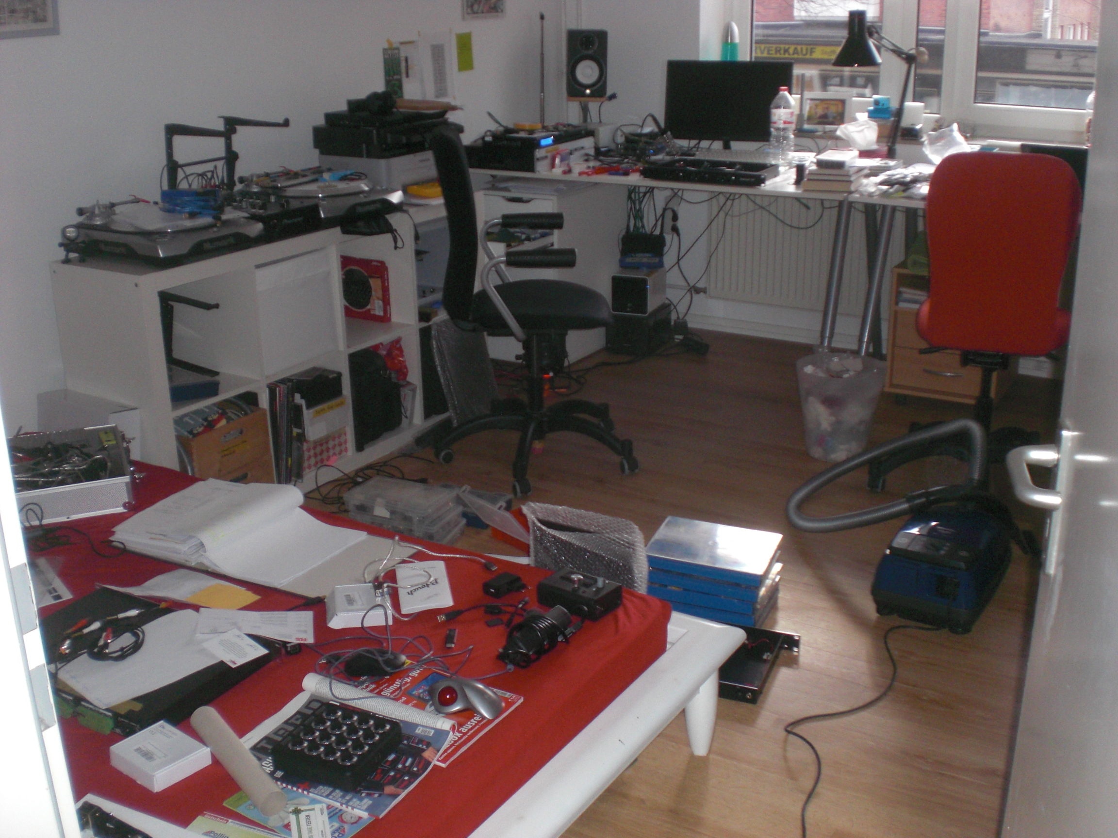
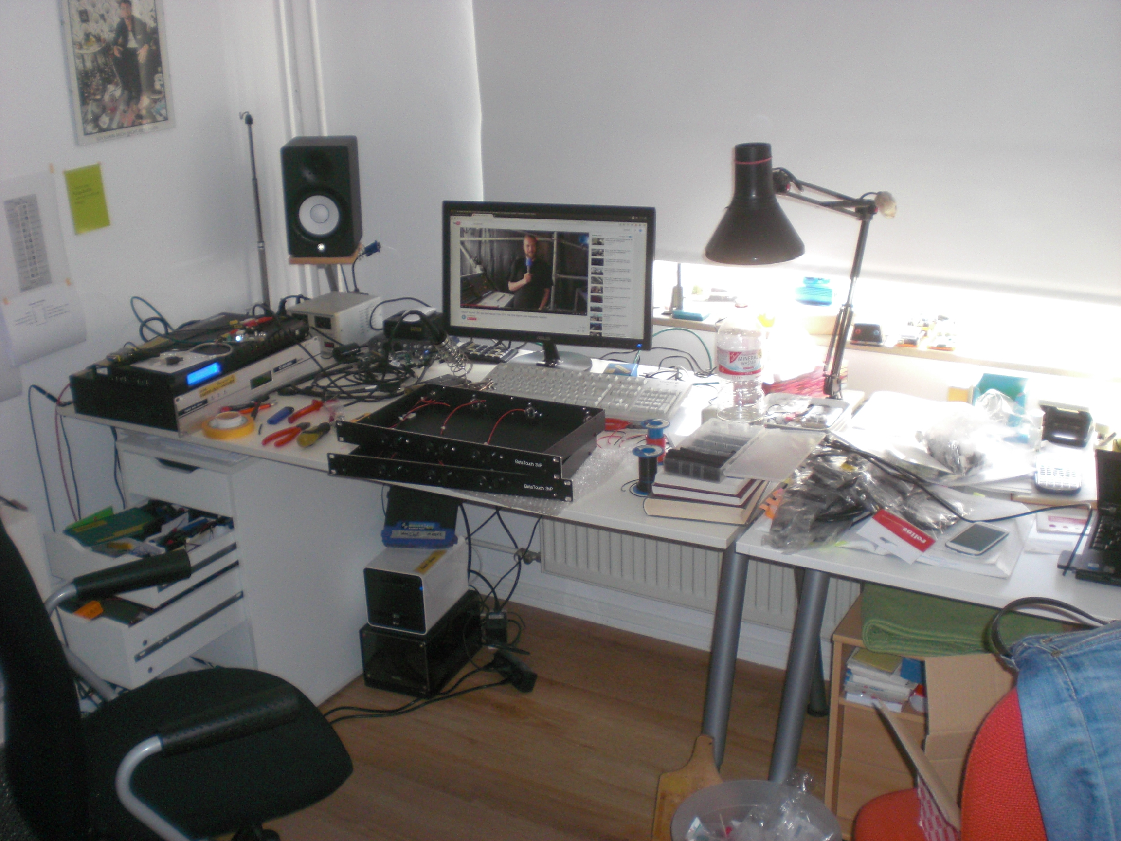
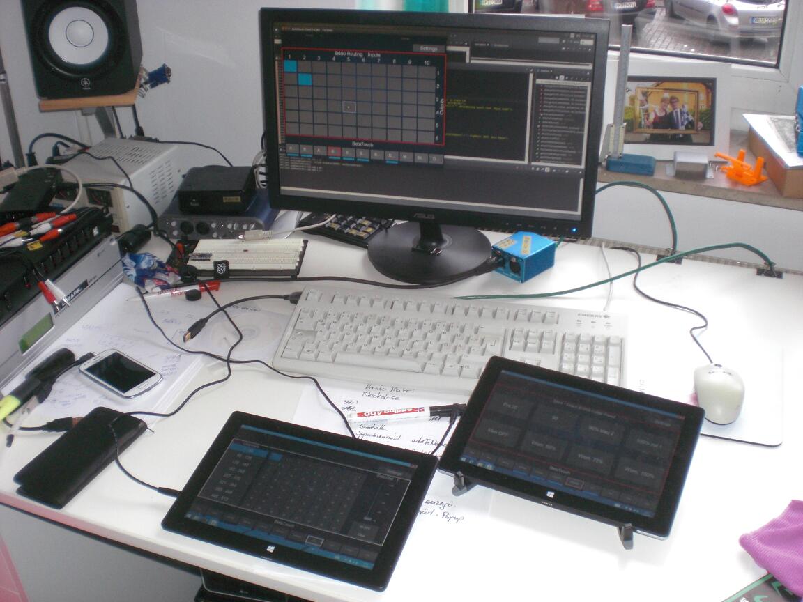
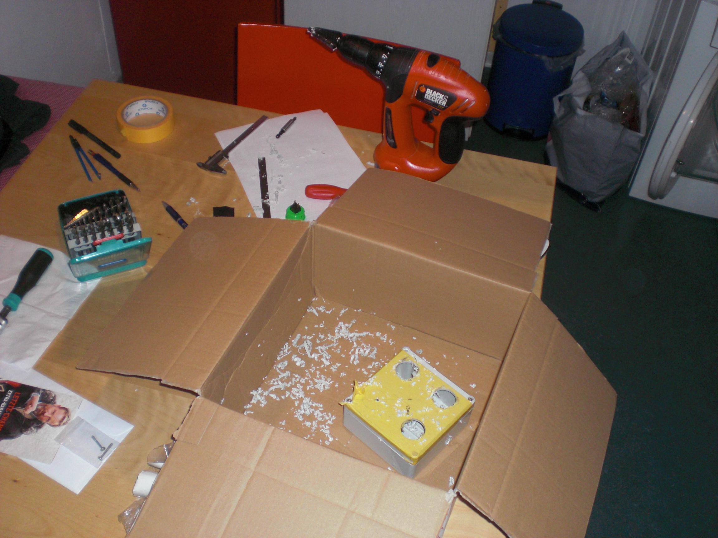
Egal. Die letzten 2 Jahre jedenfalls sah mein Schreibtisch bestenfalls so aus, sofern er aufgeräumt war:
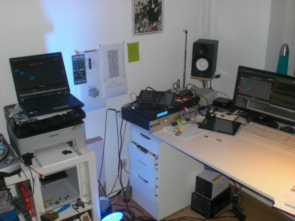
Immer (IM-MER) mindestens 3 Rechner gleichzeitig, ein Riesenhaufen Zettel mit wahllos verstreuten Notizen. Zusätzlich ein Haufen 19″ Geräte, die immer alle ausnahmslos angeschaltet sind, kilometerweise Kabel, Klebeband, Beschriftung, Lampen, ….
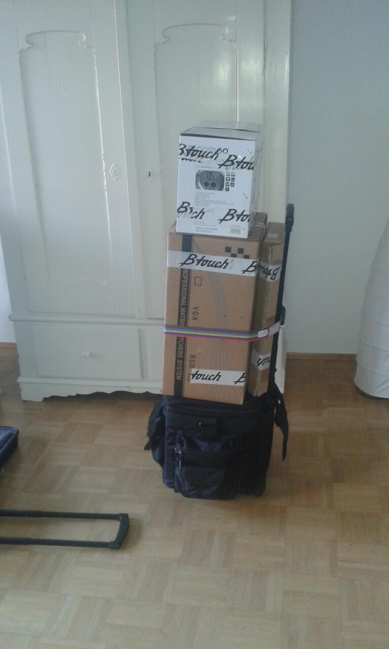
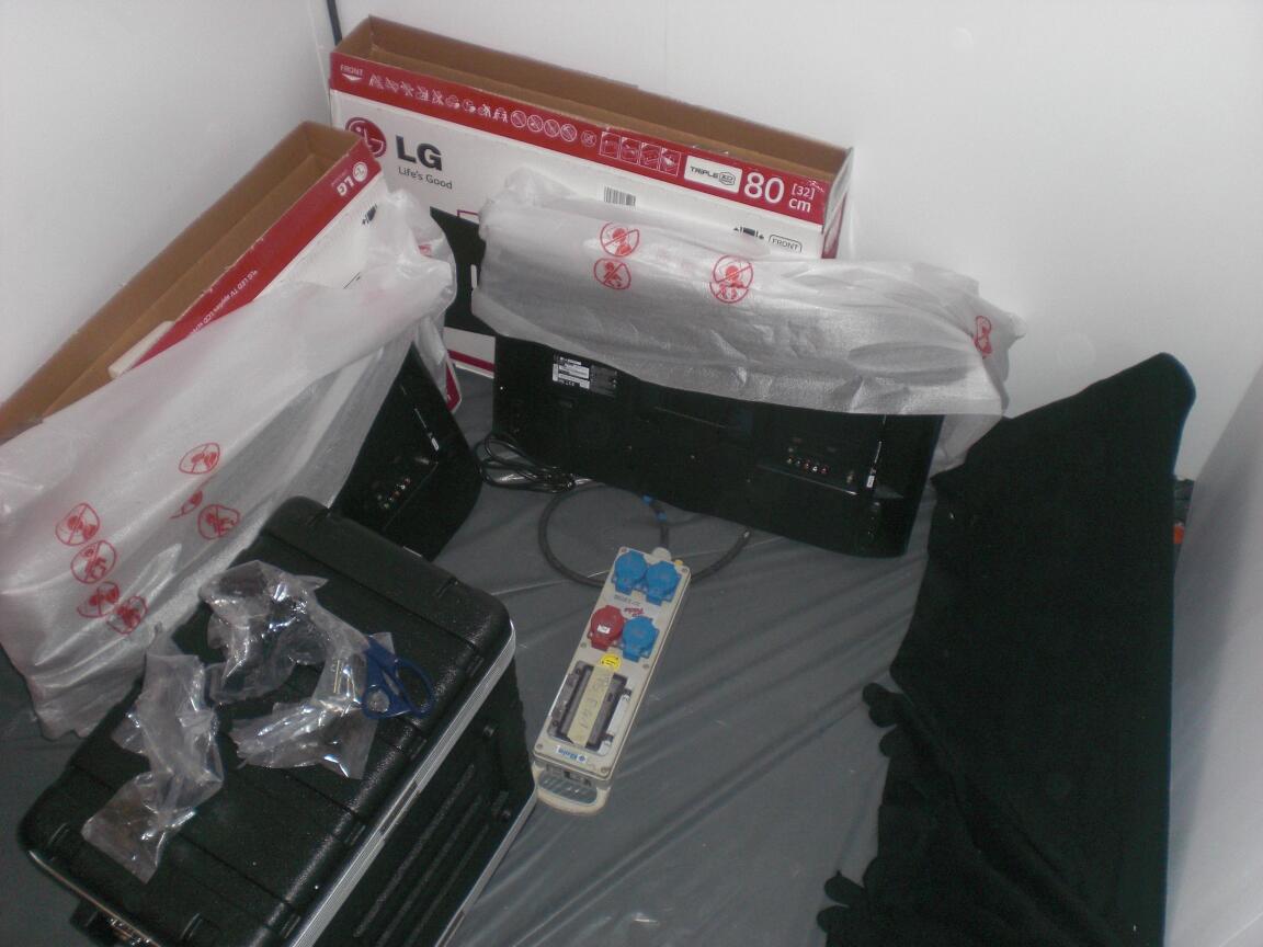
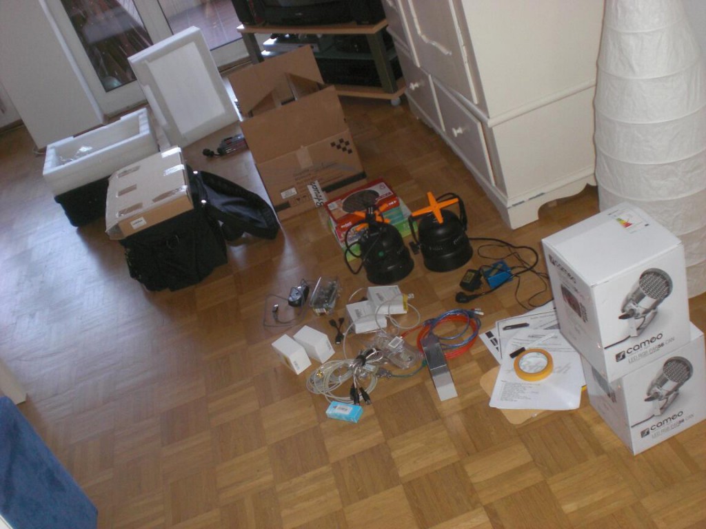
Der ganze Kram, den ich zur Messe nehmen musste: 4 Stück 19 Zoll Geräte (insgesamt 5HE), 2 Tablets, 2 LED PAR56, 2 Laptops, 1 USB Tastatur, 1 USB-auf-4-fach-seriell Wandler, Artnet-DMX Adapter, Netzwerkkabel, USB-Kabel, Zettel, CDs, Sticker, Netzteile, eine Steckdosenleiste, blahblahblah… und ein bisschen Wäsche für eine Woche, … Alles per Bahn.
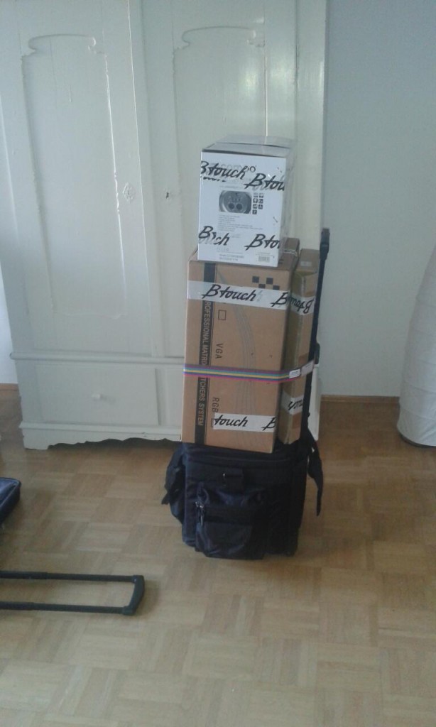
Geht. Was noch fehlt ist der Trolley mit meiner Wäsche (und der Steckdosenleiste), aber es hätte schlimmer kommen können. Nicht sonderlich viel schlimmer, aber … etwas schlimmer.
Und schwupp-Di-Wupp war ich in Hamburg Frankfurt.
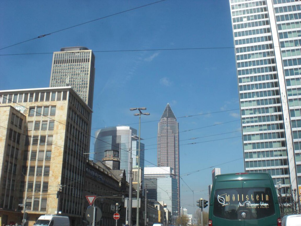
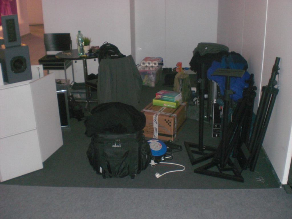
Anfangs sah das alles noch gar nicht so berauschend aus.
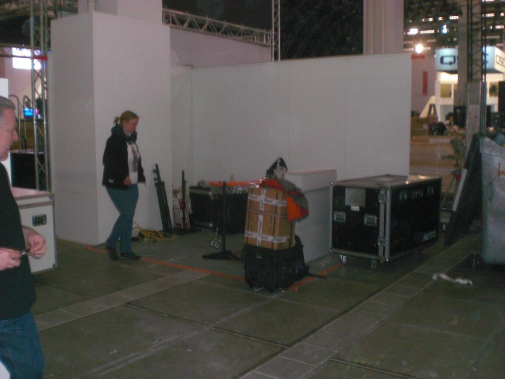
Aaaaber… das wurde noch. Um uns herum waren nur professionell gebaute Stände. Größer, bunter, mehr Zeug. Macht aber nichts. Wir haben es überhaupt nicht auf Laufpublikum und Kantenfummler abgesehen, sondern hatten unsere Termine und wollten einfach präsent sein, also alles cool.
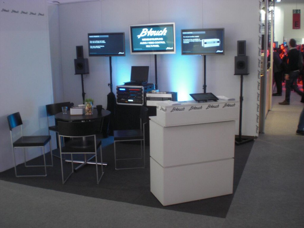
Man macht sich anfangs echt keine Gedanken darum, wie viel Aufwand eigentlich hinter so einem Messestand steckt. Ist ja schließlich nicht nur so, dass man den Stand mitsamt dem eigentlichen Kram aufbauen muss, man muss ja auch passige Präsentationen, Videos, Flyer, Visitenkarten etc. haben. Alles muss 30tausend mal gegengelesen, korrigiert, übersetzt und nochmal korrigiert (und dann nochmal gegengelesen) werden. Nach dem Aufbau ist sowieso alles ganz anders und man muss nochmal ran. Schlau ist, sich nicht vom Messerummel (speziell dem Rummel nach offiziellem Ende des Messetages) unterpflügen zu lassen. Einfach mal nicht immer der letzte auf der Standparty sein….
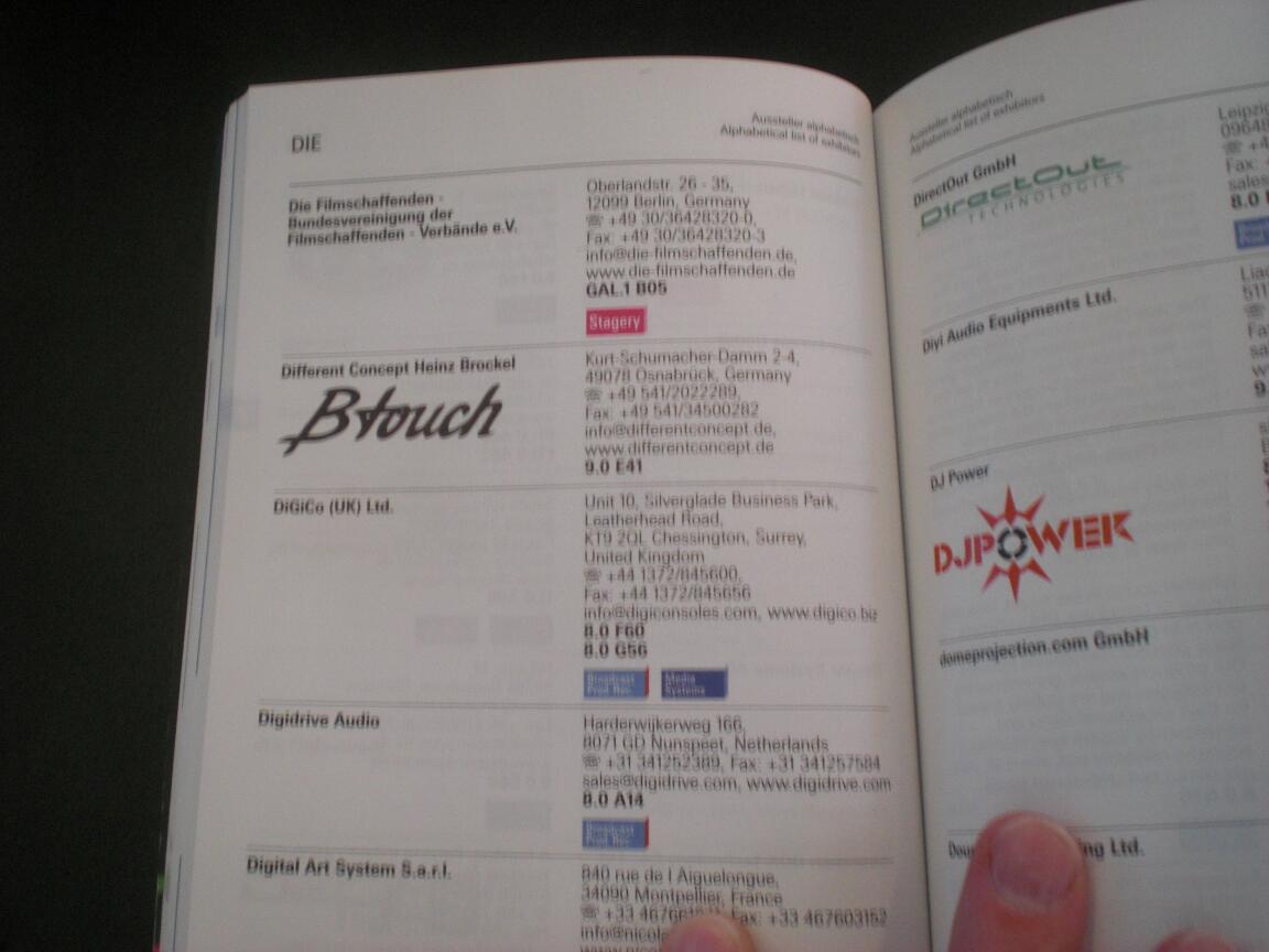
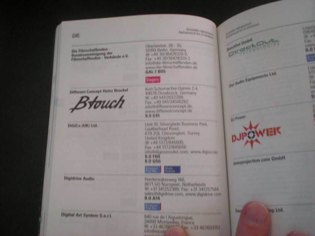
Und weil wir alles richtig gemacht haben, waren wir entsprechend auffällig im Messeverzeichnis zu finden. Nüchtern betrachtet jetzt nicht soooo das Ding. Das gibt man an die PR Abteilung ab und… ach ja… wir haben keine PR-Abteilung.
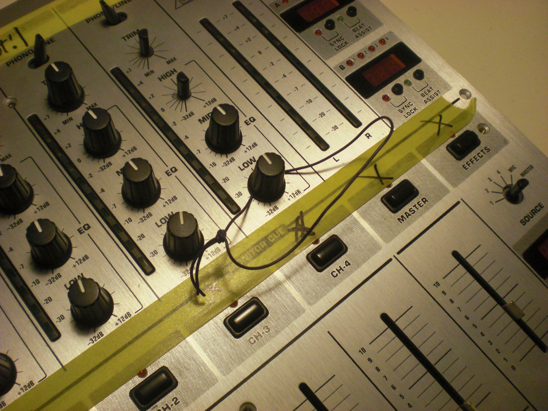
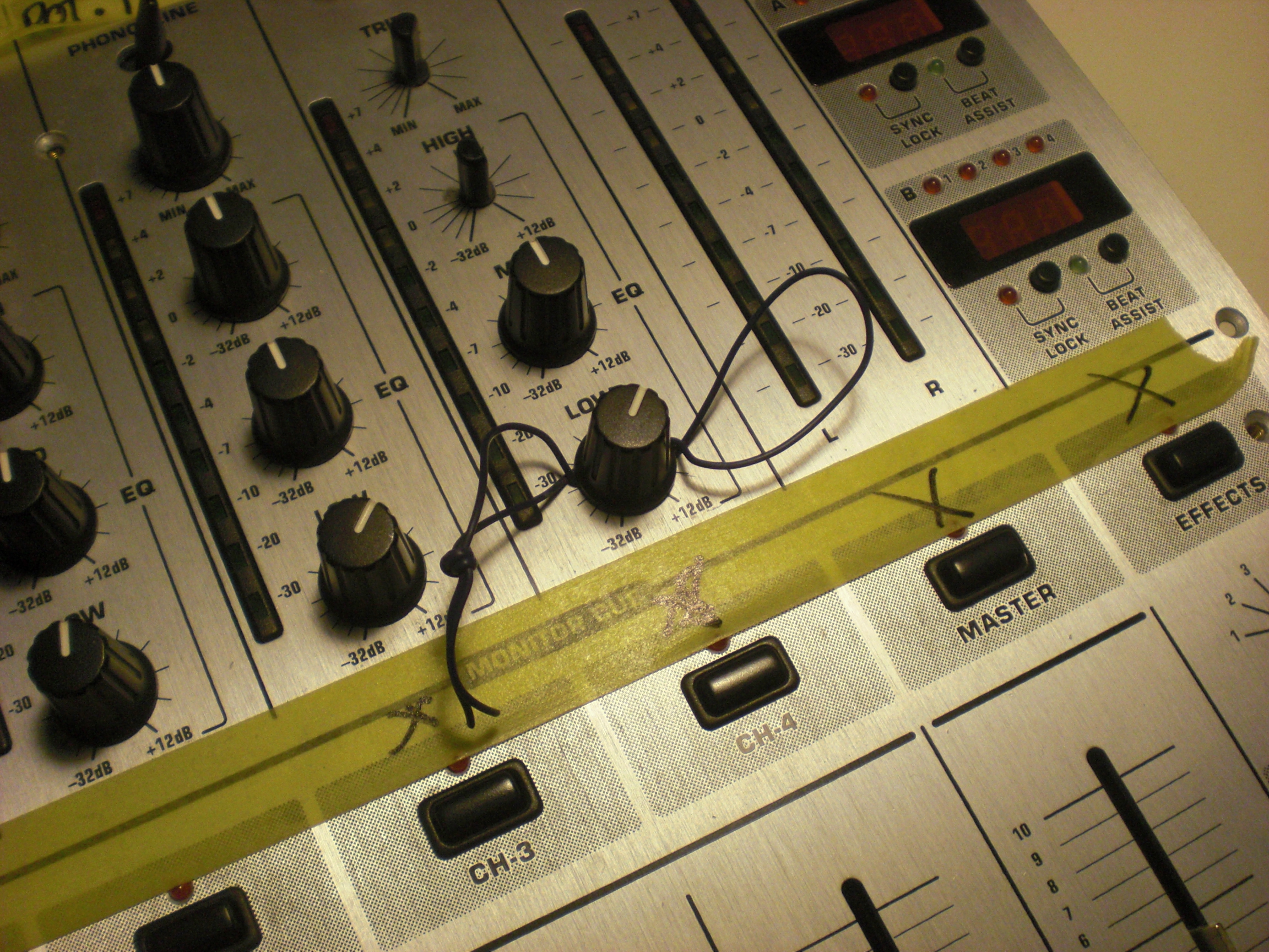
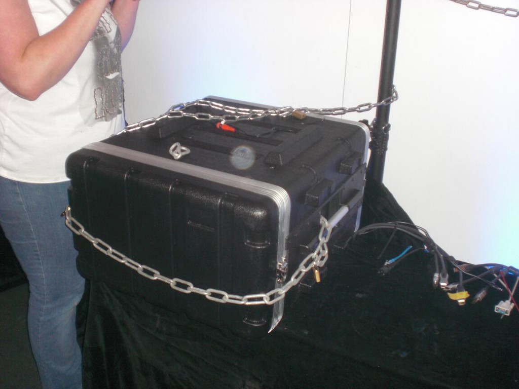
Abends den ganzen Schotter ordentlich anbinden. Man weiß ja nie. Es soll wohl Menschen geben, die mit einer klaren Definition von Eigentumsverhältnissen ihre Probleme haben.
Auch ein Vorteil von so einem kleinen Stand. Man benötigt eben keine 20 Stagehands, um das Ding innerhalb einer halben Stunde abzureißen. Flugs den alten Stand runtergeballert und in den Combi reingemöllert =) .
Fazit: Alles richtig gemacht. Alles.
Die beiden Anderen machen gerade die Nachbearbeitung (Kontakte anschreiben, Angebote zusammenstellen, Feedback koordinieren, etc).
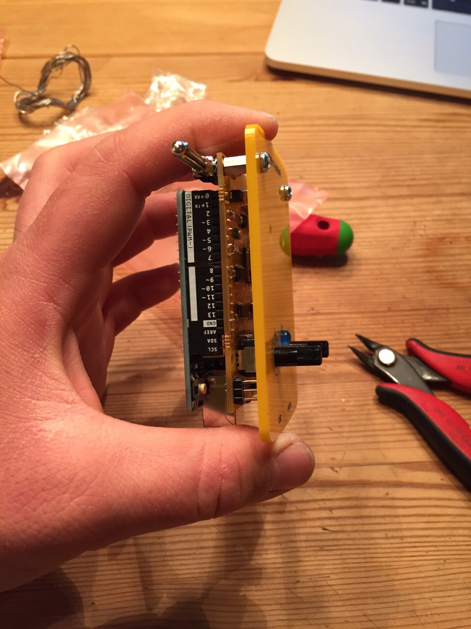
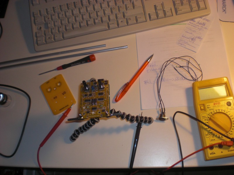
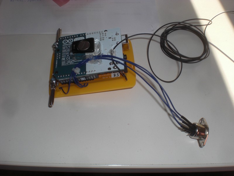
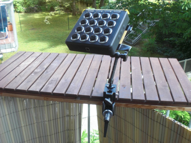
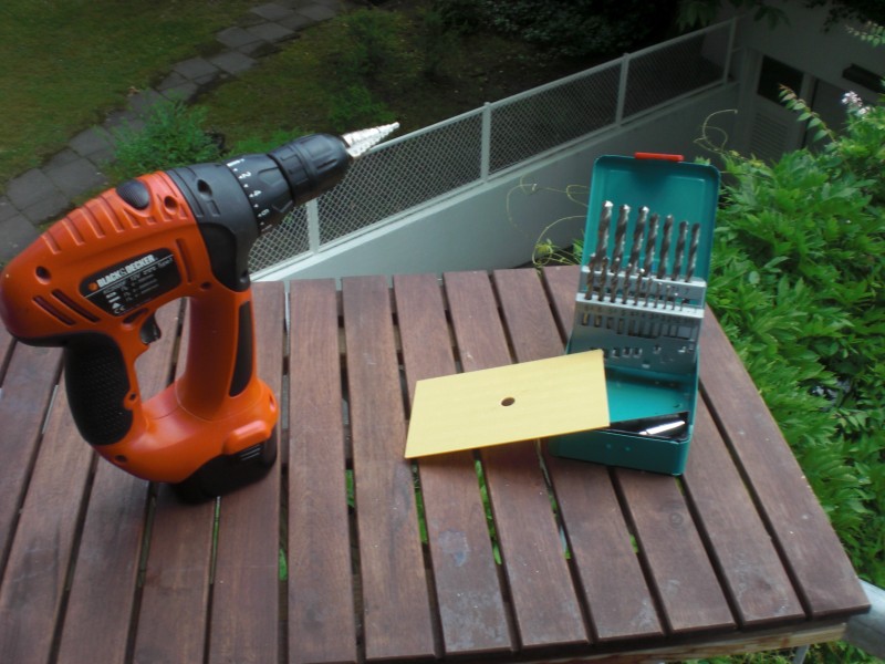
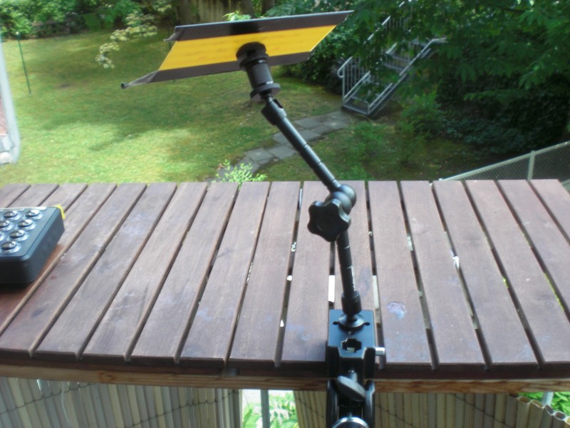
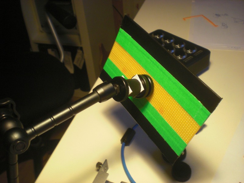
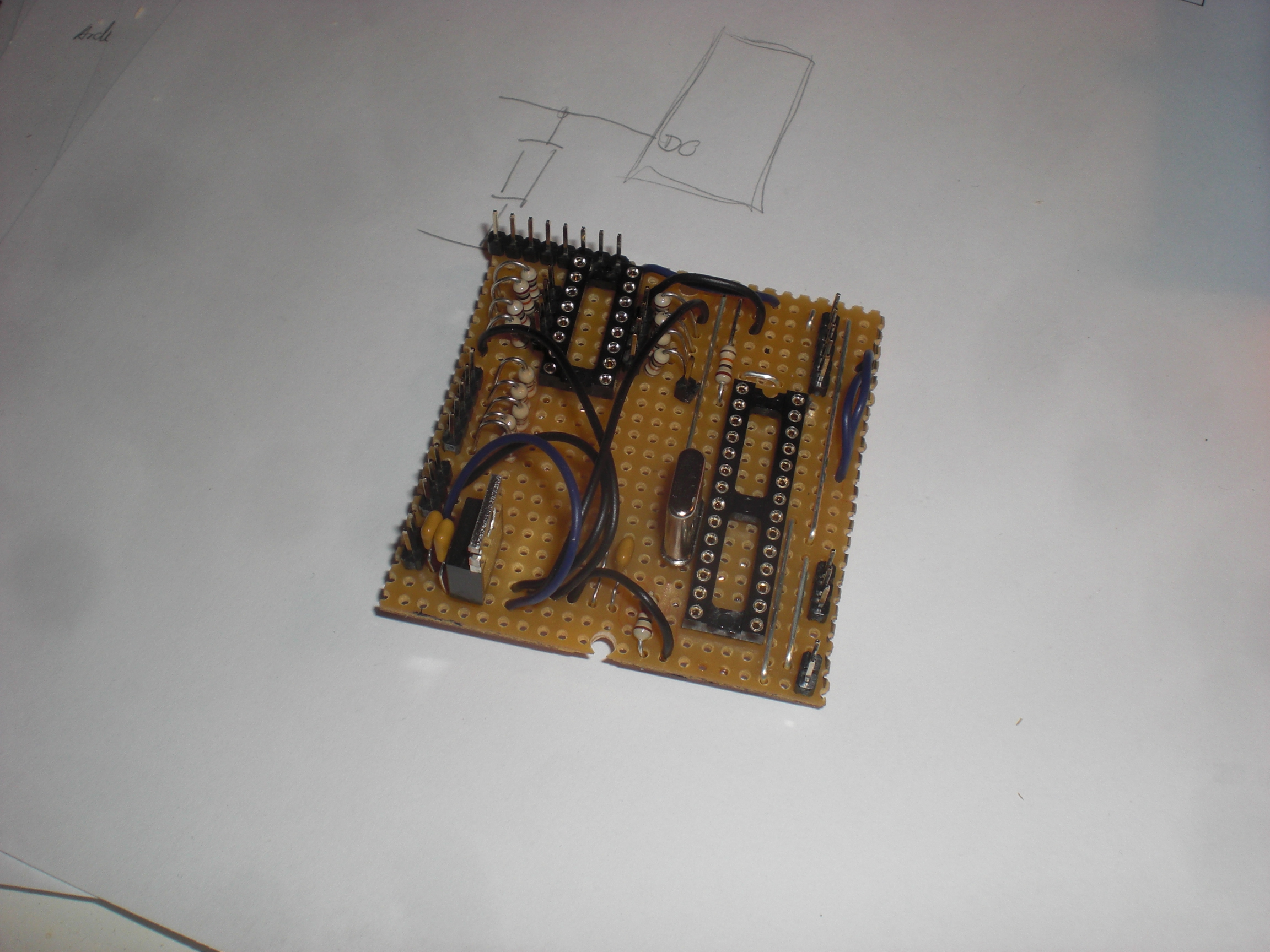
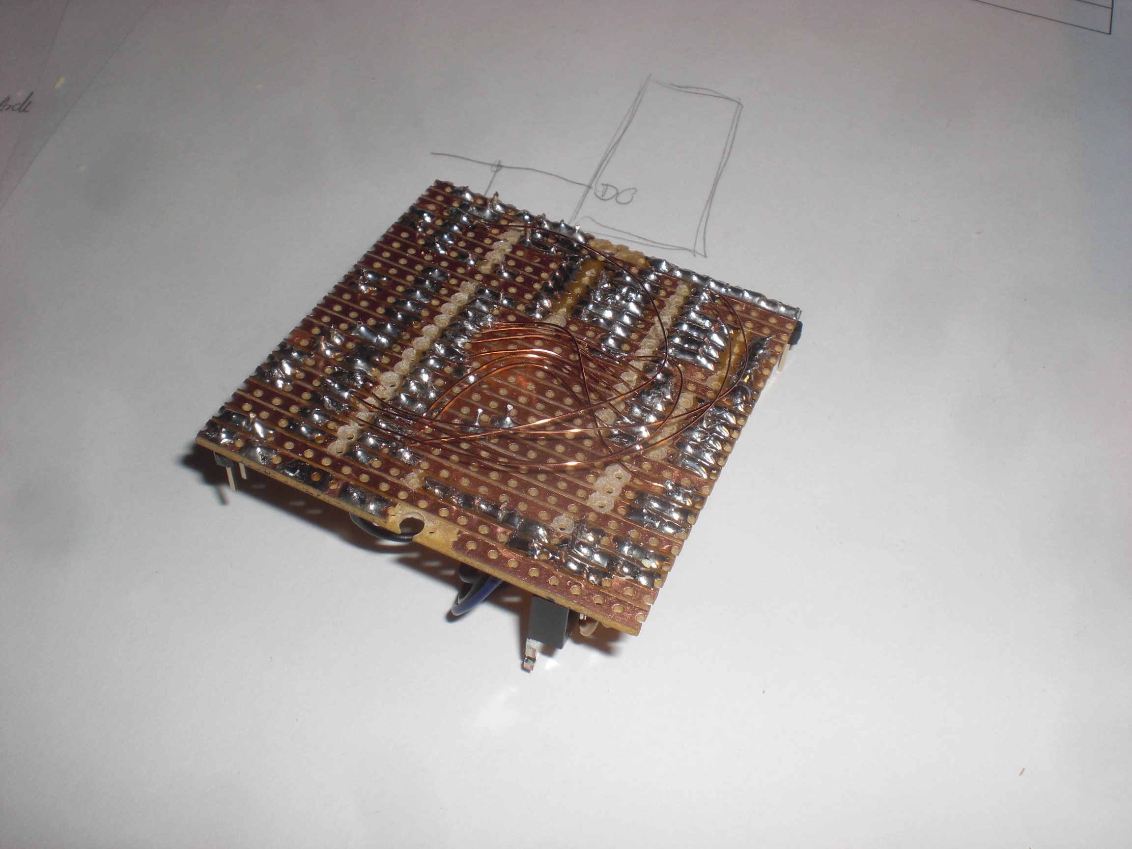
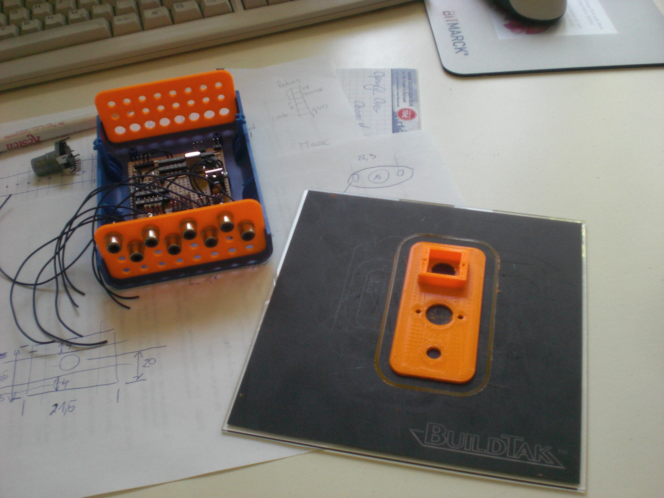
Ich gönn’ mir jetzt erst mal eine Woche Nixtun. Also “nix” im Sinne von “nur den einen Hauptjob” und nebenbei ein bisschen Spaß-Programmierung: Es liegt noch ein angefangener Erschütterungssensor-To-Midi-Konverter bei mir herum, der wird jetzt fertiggemacht. Außerdem hab’ ich noch ein bisschen was von meinem Lieblingsbier zuhause.
My trusty ol’ Behringer DJX700 has seen better days. It was still working but some things just didn’t do anymore: Channel 3’s phono input had a dead right channel, the pre-listen-selector buttons of channel 1, 3,4, main out and the fx-section had some faulty contacts. The crossfader was exchanged ~1 year back so that was working still fine. the line faders were also running smooth and without any problems.
In order to get an idea about what’s going on inside the mixer I had to remove the front panel. Using some leftovers of thin cable to remove the caps was one of the better ideas I had that day.
The inside view didn’t surprise me too much. It’s Behringer so you know there will be hot glue inside. Lots of hot glue.
Fortunately, Santa Claus brought us a new hairdryer which I could use to soften and remove the glue between the connectors (don’t let my SO know about this).
Of course: I am the one to get scratches from using hot glue and a hairdryer
That’s the naked board. Not too much to see here.
At first I thought about replacing the faulty buttons with new ones but I really didn’t have enough energy to look out for (and order) the correct buttons…..
…that’s why I slaughtered the frequency-kill-buttons left and right of the crossfader. I really don’t think anybody besides EDM DJs uses these to a noticeable amount. If you want to cut frequencies there is still the ordinary eq-section left, after all.
Neither did I repair the broken phono input. I just made sure it’s obvious to not use it anymore withe Behringer’s best: hot glue.
Only a few leftovers. Everything’s cool.
Recapturing this post I have to admit that ‘refurbishing’ might be the incorrect term for what happened here =).
…für ganz Arme…. Oh manno…
Als wir in die Bude hier eingezogen sind, habe ich nicht aufgepasst und deswegen haben wir keinen brauchbaren Keller, sondern nur einen stromlosen, absolut unbrauchbaren Gitterverschlag, in dem man natürlich nicht mal eben fix was bohren, sägen oder gar in Ruhe bauen kann. Deswegen muss ich mir irgendwie helfen.
Jetzt gerade isses Winter. Das ist derzeit (Januar 2015) zwar kein Garant für ‘draußen kalt’, aber ich muss mehrere solcher Kästchen bauen und auf’m Balkon geht das gar nicht. Im Arbeitszimmer sowieso nicht und deswegen bleibt nur noch die Küche (“Wir haben eine Küche?”).
Und weil ich eben nicht wollte, dass überall diese klebrigen Kunststoffkrümel herumfliegen, … seht selbst: Granatenidee. Läuft bei mir.
Or: Creating an audio-signal with an Arduino, feeding it into a mixing desk, altering the frequencies via the mixer’s eq and analyzing the processed audio with another Arduino which then turns it into a MIDI-signal. Yes, that is Digital-to-Analog-to-Digital-to-Analog-to-Digital-conversion. Phew!
Here’s a picture of the setup:
On the left side there is a circuit consisting of an Arduino and an Attiny85. The Arduino creates a low-frequency ( ‘bass’ ) sine-shaped tone which perfectly sits in the frequency range of the mixer’s bass-EQ. I did some testing here to find the perfect frequency. Testing means: Using Ableton Live to create a white noise, feed this into the mixer, feed the mixer’s output back into Ableton and use the Spectrum-tool to see which frequency gets most influenced by the bass-EQ (C2, that is).
Creating a somewhat true sine needs some effort since the Arduino’s analog outputs only do PWM which isn’t very useful when talking about low-frequency audio signals. PWM basically creates a square-wave signal with a certain pulse-pause relation. While this might be okay for dimming an LED, this becomes quite unusable when dealing with audio because you can simply hear that it’s no sine – the lower the frequency the more the signal turns into some sort of ‘click’-noise. No wonder, the bass-EQ doesn’t influence this to any convience.
That’s why I used this solution to make the Arduino spit out something that’s a little more sinewave-like. I ommitted the circuit as you may see on the picture below. I didn’t have the necessary parts lying around and it worked nevertheless.
The Attiny85 is used to create the second tone. It’s a simple PWM signal at 480 Hz. This time the PWM-nature of the signal can be used for our benefits: A square-wave signal has a recognizable amount of harmonics. You don’t hear one but (at least) two tones. Perfect for us because the mixer I used perfectly influences (well … “perfectly” ) the signals with its mid- and hi-EQs.
The code for the Attiny85 looks like this:
void setup(){
pinMode(3, OUTPUT);
}
void loop(){
buzz(3,480,100);
}
void buzz(int targetPin, long frequency, long length) {
long delayValue = 1000000/frequency/2; // calculate the delay value between transitions
long numCycles = frequency * length/ 1000; // calculate the number of cycles for proper timing
for (long i=0; i < numCycles; i++){ // for the calculated length of time…
digitalWrite(targetPin,HIGH); // write the buzzer pin high to push out the diaphram
delayMicroseconds(delayValue); // wait for the calculated delay value
digitalWrite(targetPin,LOW); // write the buzzer pin low to pull back the diaphram
delayMicroseconds(delayValue); // wait again or the calculated delay value
}
}
I guess I found it over here and adapted it to my needs.
the two microcontroller’s output signals are fed into a 7408 (Quad AND) and then sent out into the analog world by a circuit I found over at the MunichMakerLab. This is my first audio-circuit with an Arduino. it’s probably spine-crawling for those who do this on a more professional base but I was getting the best results with this circuit.
[Edit] As someone pointed out in the comments section for this post on Hackaday this might read like I didn’t know at all what I am doing here or that it’s all just a big coincidence. This is not correct. The AND gate protects the audio sources from interfering with each other for a certain amount. I tested that, it simply sounds cleaner. At least I had a certain intention when I added the gates to the circuit (…not that I completely remember….). Looking at the circuit I am still wandering about _why_ but that’s one of the things that I file as ‘Audio things’ for now. [/Edit]
The signal is fed into the mixer and from the mixer sent to another Arduino which does the processing. the circuit looks like this:
To be honest: I cannot really remember where I got this circuit from. Somehow all the solutions I found while trying to find the circuit again look a little different. Again this might be spine.crawling for some of you but… it’s a fun project and it works. The code for the realtime audio-analysis is based on the FHT library by openmusiclabs and expands an example I found over at dontquityourdayjob.
/////////////////////////////////////////////////////////////////////
// Easy Customizations
/////////////////////////////////////////////////////////////////////
// Adjust the Treshold – what volume should make it light up?
#define THRESHOLD 40
// Attempt to ‘zero out’ noise when line in is ‘quiet’. You can change this to make some segments more sensitive.
int oct_bias[] = { 600, 600, 1, 100, 50, 50, 50, 50 };
// Divide Threshold by 2 for top octave? 1 – yes 2 – no. Makes highest frequency blink more.
#define TOP_OCTAVE_DIVIDE false
/////////////////////////////////////////////////////////////////////
// Hard Customizations – know what you are doing, please.
/////////////////////////////////////////////////////////////////////
// FHT defaults – don’t change without reading the Open Music Labs documentation at openmusiclabs.com
#define LOG_OUT 0 // use the log output function
#define FHT_N 256 // set to 256 point fht
#define OCTAVE 1
#define OCT_NORM 1
// Delay – defines how many cycles before the lights will update. OML’s algorithm at 256 samples (needed for our 8 octaves) takes
// 3.18 ms per cycle, so we essentially throw out 14 cycles (I used mechanical relays, you can lower this for solid state relays).
// 15 cycles = 47.7 ms update rate. Be careful here and don’t change it too quickly! I warned you!
#define DELAY 15
#include <FHT.h> // include the library
#include <MIDI.h>
void setup() {
Serial.begin(31250); // use the serial port
TIMSK0 = 0; // turn off timer0 for lower jitter
ADCSRA = 0xe5; // set the adc to free running mode
ADMUX = 0x40; // use adc0
DIDR0 = 0x01; // turn off the digital input for adc0
}
/**********************************************************************************
Loop – includes initialization function and the full loop
**********************************************************************************/
const int NUMREADINGS=10;
int readings[NUMREADINGS]; // the readings from the analog input
int index = 0; // the index of the current reading
int total = 0; // the running total
int average = 0;
int bassVal;
int midVal;
int hiVal;
int bassValOld;
int midValOld;
int hiValOld;
const int OUTTHRESHHOLD = 4;
void loop() {
// True full loop
int q = 0;
while(1) { // reduces jitter
cli(); // UDRE interrupt slows this way down on arduino1.0
for (int i = 0 ; i < FHT_N ; i++) { // save 256 samples
while(!(ADCSRA & 0x10)); // wait for adc to be ready
ADCSRA = 0xf5; // restart adc
byte m = ADCL; // fetch adc data
byte j = ADCH;
int k = (j << 8) | m; // form into an int
k -= 0x0200; // form into a signed int
k <<= 6; // form into a 16b signed int
fht_input[i] = k; // put real data into bins
}
fht_window(); // window the data for better frequency response
fht_reorder(); // reorder the data before doing the fht
fht_run(); // process the data in the fht
fht_mag_octave(); // take the output of the fht
sei();
if (q % DELAY == 0) {
//—-Smoothing
// subtract the last reading:
total= total – readings[index];
// read from the sensor:
readings[index] = (fht_oct_out[1] – oct_bias[1]);
// add the reading to the total:
total= total + readings[index];
// advance to the next position in the array:
index = index + 1;
// if we’re at the end of the array…
if (index >= NUMREADINGS)
// …wrap around to the beginning:
index = 0;
// calculate the average:
average = total / NUMREADINGS;
//—-
//Werte:
bassVal = average; // : Bass
midVal = fht_oct_out[4] – oct_bias[4]; // Mitte
hiVal = fht_oct_out[7] – oct_bias[7]; //Hochton
bassVal = map(bassVal, -450, -390, 0, 127);
midVal = map(midVal, 9, 107, 0, 127);
hiVal = map(hiVal, -34, 20, 0, 127);
if((bassVal > bassValOld+OUTTHRESHHOLD) || (bassVal < bassValOld-OUTTHRESHHOLD)){
if((bassVal>=0) && (bassVal<=127)){
Serial.write(0xb0);
Serial.write(0x01);
Serial.write(bassVal);
}
bassValOld = bassVal;
}
if((midVal > midValOld+OUTTHRESHHOLD) || (midVal < midValOld-OUTTHRESHHOLD)){
if((midVal>=0) && (midVal<=127)){
Serial.write(0xb0);
Serial.write(0x02);
Serial.write(midVal);
}
midValOld = midVal;
}
if((hiVal > hiValOld+OUTTHRESHHOLD) || (hiVal < hiValOld-OUTTHRESHHOLD)){
if((hiVal>=0) && (hiVal<=127)){
Serial.write(0xb0);
Serial.write(0x03);
Serial.write(hiVal);
}
hiValOld = hiVal;
}
}
++q;
}
}
The whole mechanism is not THAT precise but it gets the job done and it’s a fun thing to watch. The bass-frequency has to be smoothed-out quite a bit in order to make it all work. After spending a little more than a day with this some might ask “what for?”. I tell you what for: for the sake of finally doing it. I had this idea for over a year now and it was well worth trying.
The system is quite slow in its reaction (mainly caused by the necessary smoothing) and results are still a bit unpredictable but turning an audio-mixer into a midi-controller just by using hardware of ~10€ ain’t too bad, isn’t it?
[tube]https://www.youtube.com/watch?v=u5r6i65eHKk, 720, 540[/tube]
Due to various reasons (and only some of them are cool) I haven’t done a lot of jobs as a lightjockey within the last 2 years. But destiny seems to be on my side at the moment and so I had the chance to do the lights and visuals at the ‘Graudate’s Ball 2014’ in Osnabrück. the whole event was very professionally done so it was very much like an industrial event. Dates like these are mainly characterized by a rather fixed timetabel and a somewhat limited necessity for pure creativity and next-generation-visuals. It has to work and it has to work on time. That’s why you are there, that’s what you are paid for (mostly).
The event already started with a delay. I had to get from Hamburg to Osnabrück and was more than an hour late even before anything happened at all. Fortunately I knew about the fact that most things were already set up at the venue. This was one of those jobs I’d like to describe as a ‘Kofferjob’. Get there, get out your Laptop and voila! No need for building up an entire stage structure, cabling etc.