Next Level Midi Controller, Pt. 3

Das ist die Fortsetzung vom zweiten Teil und es geht immer noch darum, Jogwheels für den neuen Midi-Controller zu bauen. Es ist zum Abflippen, aber warum muss auch alles so unglaublich kompliziert sein? Die letzte Konstruktion mit dem “Zahnrad” als Unterbrechung für Reflexionen hat sich nach längerer Überlegung als wenig brauchbar erwiesen, aber Dank ganzganzviel Fantasie kam schnell die nächste Idee und sie beginnt mit der Vermessung vong von einer Dose Kräutersalzes.

Continue reading

Next Level Midi Controller, Pt. 2

Das ist die Fortsetzung vom 1. Teil, bei dem es darum ging, einen neuen Midi-Controller zu bauen. sagen wir mal so: Es ist nicht ganz so einfach, wie ich mir das seinerzeit vorgestellt hatte. Größte Baustelle sind derzeit die Jogwheels. Ursache dafür ist, daß ich möglichst keine Spezialteile verwenden will. Wenn mal etwas kaputt geht, will ich es schnell austauschen können. Erste Idee war es, einen Drehwertgeber (“Rotary Encoder”) zu verwenden. Aus einer Zeit eher hemmungsloser Bestellungen beim Pollin habe ich noch einen Rutsch dieser Teile

Continue reading

BTouch Client Version 2

Bei der Entwicklung vom BetaTouch Client Version 1 bin ich seinerzeit ziemlich schnell an die Grenzen der Verwendeten Technologie gestoßen. Was will man machen, eine Entwicklungsumgebung, für die es damals schon seit ~15 Jahren keine Updates mehr gegeben hat, ….    macht mindestens mal bei der täglichen Arbeit absolut keinen Spaß mehr. Deswegen habe ich  um das Jahr 2013 (sofern ich mich richtig erinnere) damit begonnen, Eine bessere Version von Grund auf neu zu entwickeln.

Zu den gewollten Merkmalen gehörte eine möglichst große Flexibilität bei der Gestaltung der Oberfläche, einfache Erweiterbarkeit um neue Funktionen, Synchronisation via Netzwerk…..    und wenn’s neben Windows auch auf Linux liefe, wäre auch nicht schlecht.

Herausgekommen ist der ΒTouch Client Version 2  ( … btw: Das ist nicht der Buchstabe ‘B’, sondern ein ‘Beta’ …  #truestory ) .

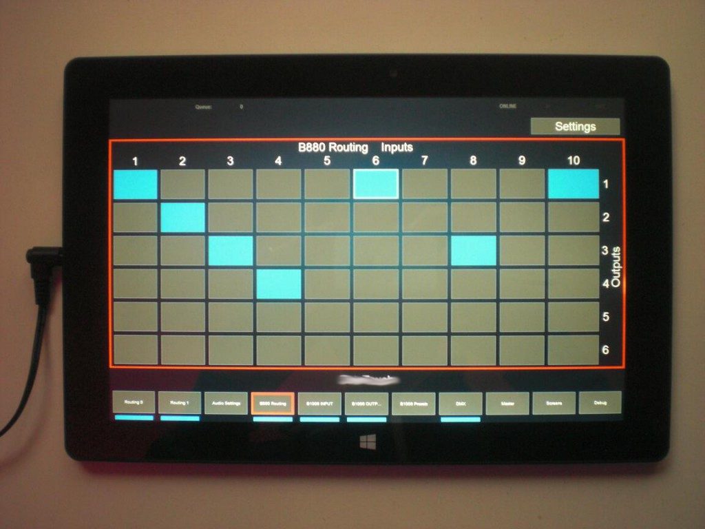
Es ärgert mich übrigens maßlos, jawohl, dass ich es verpeilt habe, mit den Feldern wenigstens für das Foto irgendeine Form von ASCII-Art darzustellen. Scheibenkleister! Aber egal:

Die Software ist darauf ausgelegt, per Touchscreen bedient zu werden. Sie erlaubt die Steuerung unterschiedlichster Geräte(-kombinationen) durch nicht-geschultes Personal. Die Software eliminiert das Risiko von Fehlbedienungen und ist in der Lage, Multiroom-fähige Steuerkonzepte zu implementieren. Geräteabhängige Steuerprotokolle, Regelsätze, etc. können darüberhinaus verhältnismäßig leicht hinzugefügt werden.

Continue reading

I2C Daisy-Chain Module (“Zauberkästchen”)

Ich hab es an anderer Stelle schon einmal erwähnt: Seit mehreren Jahren arbeite ich mit Leuten an einer Lösung zur Steuerung von Geräten. Der ganze Bimmbamm hat sehr wenig bis ganz viel mit Automatisierung zu tun, geht aber an manchen Stellen darüber hinaus und ist an an verschiedenen Stellen sowieso ganz etwas anderes. Das Ding nennt sich BetaTouch.

Einer der Wege, die wir mal verfolgt haben, waren die ‘Zauberkästchen’. Daraus ist kein fertiges Produkt geworden, aber es gibt ein paar Bilder und ein wenig was zu erzählen. Hervorragend also für die Webseite.

Continue reading

Midi Theremin

This project is based on the idea of my buddy Matthias over at Visual Phi Events. The idea is simple: “Let’s do something with a Theremin controlling visuals. That’d be cool.”. Well, it surely is…

Fortunately we didn’t have to buy an original Theremin (for the price of an original Theremin) but could base our idea on the work of the Open Theremin Uno project.

IMG-20150517-WA0001

IMG-20150517-WA0000

CIMG0432

Adding Midi to the Theremin circuit is as easy as soldering 3 wires to the board. Since it’s all based on the Arduino Uno it’s easier to link to the article on the Arduino website than writing it down myself.

CIMG0435

For the first basic tests I connected the Theremin to a simple zoom-effect in VDMX:

The finished project was set up at the Sabinchenfest in Treuenbrietzen.

CIMG0440

The two possible Midi data-streams (one corresponding to the Theremin tone’s pitch, the other one to the volume) were connected with a simple Quartz-Composer patch, controlling the angles of a cube. That was cool.

Motion-Sensor-to-MIDI-Converter

An idea that came up during the 31C3. The guys from VisualPhi had some motion sensors lying around and wanted to use them to control their VJ-software. That’s why I built them a Motion-Sensor-to-MIDI-Converter.

As usual it all starts on a breadboard. Most of the times I draw the schematics parallel to building the circuit on a breadboard. Guess that’s the usual way.

CIMG0230


The circuit itself is rather unspectacular. 8 inputs are polled from a 74HC165. Then there’s a little bit of logic implemented within an Arduino and then there’s 16 LEDs, a rotary encoder and MIDI out.

CIMG0231


CIMG0233


This project is the first one to benefit from my new 3D Printer. Due to the fact that I don’t have a dedicated toolshed anymore it’s kind of impossible to reliably manufacture the case anymore. Seems as if I don’t need one from now on.

CIMG0261


I really think the fixation of the rotary encoder is one of the smartest pieces ever done by mankind. Ever =)

CIMG0264


CIMG0263


The LEDs are driven via Charlieplexing. It’s rather easy to implement but you really need to concentrate while soldering. By the way: If everything else fails I guess I’ll become a Soldering-Artist one day.

CIMG0269


The function of the device is easy to explain. Every input is triggered when the state of a connected switch changes. This is indicated by the red LED below the channel. The green LEDs indicate the channel that’s influenced by the rotary enoder: The encoder gives the possibility to set the time that has to pass from the moment the input is triggered until it can be retriggered again. Something like a ‘Retrigger Threshold’. The value can be set to values between 0 and ~2 seconds. When the lower / upper limit of the value is reached the green LED flashes. Pressing the rotary encoder (it has a built-in switch) switches to the next input.

A triggered input sends a MIDI note.

CIMG0266


CIMG0276


CIMG0275

Arduino Audio-To-Midi

Or: Creating an audio-signal with an Arduino, feeding it into a mixing desk, altering the frequencies via the mixer’s eq and analyzing the processed audio with another Arduino which then turns it into a MIDI-signal. Yes, that is Digital-to-Analog-to-Digital-to-Analog-to-Digital-conversion. Phew!

Here’s a picture of the setup:

CIMG9954

On the left side there is a circuit consisting of an Arduino and an Attiny85. The Arduino creates a low-frequency ( ‘bass’ ) sine-shaped tone which perfectly sits in the frequency range of the mixer’s bass-EQ. I did some testing here to find the perfect frequency. Testing means: Using Ableton Live to create a white noise, feed this into the mixer, feed the mixer’s output back into Ableton and use the Spectrum-tool to see which frequency gets most influenced by the bass-EQ (C2, that is).

Creating a somewhat true sine needs some effort since the Arduino’s analog outputs only do PWM which isn’t very useful when talking about low-frequency audio signals. PWM basically creates a square-wave signal with a certain pulse-pause relation. While this might be okay for dimming an LED, this becomes quite unusable when dealing with audio because you can simply hear that it’s no sine – the lower the frequency the more the signal turns into some sort of ‘click’-noise. No wonder, the bass-EQ doesn’t influence this to any convience.

That’s why I used this solution to make the Arduino spit out something that’s a little more sinewave-like. I ommitted the circuit as you may see on the picture below. I didn’t have the necessary parts lying around and it worked nevertheless.

The Attiny85 is used to create the second tone. It’s a simple PWM signal at 480 Hz. This time the PWM-nature of the signal can be used for our benefits: A square-wave signal has a recognizable amount of harmonics. You don’t hear one but (at least) two tones. Perfect for us because the mixer I used perfectly influences (well … “perfectly” )  the signals with its mid- and hi-EQs.


The code for the Attiny85 looks like this:

void setup(){
pinMode(3, OUTPUT);
}

void loop(){
buzz(3,480,100);
}

void buzz(int targetPin, long frequency, long length) {
long delayValue = 1000000/frequency/2; // calculate the delay value between transitions
long numCycles = frequency * length/ 1000; // calculate the number of cycles for proper timing
for (long i=0; i < numCycles; i++){ // for the calculated length of time…
digitalWrite(targetPin,HIGH); // write the buzzer pin high to push out the diaphram
delayMicroseconds(delayValue); // wait for the calculated delay value
digitalWrite(targetPin,LOW); // write the buzzer pin low to pull back the diaphram
delayMicroseconds(delayValue); // wait again or the calculated delay value
}
}

I guess I found it over here and adapted it to my needs.

the two microcontroller’s output signals are fed into a 7408 (Quad AND) and then sent out into the analog world by a circuit I found over at the MunichMakerLab. This is my first audio-circuit with an Arduino. it’s probably spine-crawling for those who do this on a more professional base but I was getting the best results with this circuit.

[Edit] As someone pointed out in the comments section for this post on Hackaday this might read like I didn’t know at all what I am doing here or that it’s all just a big coincidence. This is not correct. The AND gate protects the audio sources from interfering with each other for a certain amount. I tested that, it simply sounds cleaner. At least I had a certain intention when I added the gates to the circuit (…not that I completely remember….). Looking at the circuit I am still wandering about _why_ but that’s one of the things that I file as ‘Audio things’ for now. [/Edit]

CIMG9964


The signal is fed into the mixer and from the mixer sent to another Arduino which does the processing. the circuit looks like this:

CIMG9963

To be honest: I cannot really remember where I got this circuit from. Somehow all the solutions I found while trying to find the circuit again look a little different. Again this might be spine.crawling for some of you but… it’s a fun project and it works. The code for the realtime audio-analysis is based on the FHT library by openmusiclabs and expands an example I found over at dontquityourdayjob.

/////////////////////////////////////////////////////////////////////
// Easy Customizations
/////////////////////////////////////////////////////////////////////

// Adjust the Treshold – what volume should make it light up?
#define THRESHOLD 40
// Attempt to ‘zero out’ noise when line in is ‘quiet’.  You can change this to make some segments more sensitive.
int  oct_bias[] = { 600, 600, 1, 100, 50, 50, 50, 50  };
// Divide Threshold by 2 for top octave? 1 – yes 2 – no.  Makes highest frequency blink more.
#define TOP_OCTAVE_DIVIDE false

/////////////////////////////////////////////////////////////////////
// Hard Customizations – know what you are doing, please.
/////////////////////////////////////////////////////////////////////
// FHT defaults – don’t change without reading the Open Music Labs documentation at openmusiclabs.com
#define LOG_OUT 0 // use the log output function
#define FHT_N 256 // set to 256 point fht
#define OCTAVE 1
#define OCT_NORM 1

// Delay – defines how many cycles before the lights will update.  OML’s algorithm at 256 samples (needed for our 8 octaves) takes
// 3.18 ms per cycle, so we essentially throw out 14 cycles (I used mechanical relays, you can lower this for solid state relays).
// 15 cycles = 47.7 ms update rate.  Be careful here and don’t change it too quickly!  I warned you!
#define DELAY 15
#include <FHT.h> // include the library
#include <MIDI.h>

void setup() {
Serial.begin(31250); // use the serial port
TIMSK0 = 0; // turn off timer0 for lower jitter
ADCSRA = 0xe5; // set the adc to free running mode
ADMUX = 0x40; // use adc0
DIDR0 = 0x01; // turn off the digital input for adc0
}

/**********************************************************************************
Loop – includes initialization function and the full loop
**********************************************************************************/
const int NUMREADINGS=10;
int readings[NUMREADINGS];      // the readings from the analog input
int index = 0;                  // the index of the current reading
int total = 0;                  // the running total
int average = 0;

int bassVal;
int midVal;
int hiVal;

int bassValOld;
int midValOld;
int hiValOld;

const int OUTTHRESHHOLD = 4;

void loop() {
// True full loop
int q = 0;
while(1) { // reduces jitter
cli();  // UDRE interrupt slows this way down on arduino1.0
for (int i = 0 ; i < FHT_N ; i++) { // save 256 samples
while(!(ADCSRA & 0x10)); // wait for adc to be ready
ADCSRA = 0xf5; // restart adc
byte m = ADCL; // fetch adc data
byte j = ADCH;
int k = (j << 8) | m; // form into an int
k -= 0x0200; // form into a signed int
k <<= 6; // form into a 16b signed int
fht_input[i] = k; // put real data into bins
}
fht_window(); // window the data for better frequency response
fht_reorder(); // reorder the data before doing the fht
fht_run(); // process the data in the fht
fht_mag_octave(); // take the output of the fht

sei();
if (q % DELAY == 0) {
//—-Smoothing
// subtract the last reading:
total= total – readings[index];
// read from the sensor:
readings[index] = (fht_oct_out[1] – oct_bias[1]);
// add the reading to the total:
total= total + readings[index];
// advance to the next position in the array:
index = index + 1;

// if we’re at the end of the array…
if (index >= NUMREADINGS)
// …wrap around to the beginning:
index = 0;

// calculate the average:
average = total / NUMREADINGS;
//—-

//Werte:
bassVal = average;                                        // : Bass
midVal = fht_oct_out[4] – oct_bias[4];    // Mitte
hiVal = fht_oct_out[7] – oct_bias[7];        //Hochton

bassVal = map(bassVal, -450, -390, 0, 127);
midVal = map(midVal, 9, 107, 0, 127);
hiVal = map(hiVal, -34, 20, 0, 127);

if((bassVal > bassValOld+OUTTHRESHHOLD) || (bassVal < bassValOld-OUTTHRESHHOLD)){
if((bassVal>=0) && (bassVal<=127)){
Serial.write(0xb0);
Serial.write(0x01);
Serial.write(bassVal);
}
bassValOld = bassVal;
}

if((midVal > midValOld+OUTTHRESHHOLD) || (midVal < midValOld-OUTTHRESHHOLD)){
if((midVal>=0) && (midVal<=127)){
Serial.write(0xb0);
Serial.write(0x02);
Serial.write(midVal);
}
midValOld = midVal;
}

if((hiVal > hiValOld+OUTTHRESHHOLD) || (hiVal < hiValOld-OUTTHRESHHOLD)){
if((hiVal>=0) && (hiVal<=127)){
Serial.write(0xb0);
Serial.write(0x03);
Serial.write(hiVal);
}
hiValOld = hiVal;
}
}
++q;
}
}


The whole mechanism is not THAT precise but it gets the job done and it’s a fun thing to watch. The bass-frequency has to be smoothed-out quite a bit in order to make it all work. After spending a little more than a day with this some might ask “what for?”. I tell you what for: for the sake of finally doing it. I had this idea for over a year now and it was well worth trying.

The system is quite slow in its reaction (mainly caused by the necessary smoothing) and results are still a bit unpredictable but turning an audio-mixer into a midi-controller just by using hardware of ~10€ ain’t too bad, isn’t it?


[tube]https://www.youtube.com/watch?v=u5r6i65eHKk, 720, 540[/tube]