Ghetto Smartphone Halter

Mannmannmann, der erste Post seit über einem halben Jahr. Kann man nichts ändern, die Praxis Dr. Andy hat einfach alle Termine belegt =). Nun gut.

Ich entwickle gerade eine Software, die unter anderem per OSC mit der Aussenwelt kommunizieren soll. Nicht nur deswegen habe ich mich in letzter Zeit verstärkt mit dem Thema auseinander gesetzt und bin natürlich auf TouchOsc gestoßen, keine Frage. Ein ausgemustertes Smartphone hatte ich noch herumliegen, also flugs die App installiert und Feuer frei. Nach 1 Sekunde merkt man aber, dass es überhaupt keinen Spass macht, wenn das Smartphone mit TouchOsc dann beim herumspielen immer irgendwo herumliegt. Da ich kein Auto besitze und noch nie einen Halter für ein Smartphone besessen habe, musste ich schnell einen bauen (wenn, dann muss das alles auch ganzganzschnellunbedingtJETZT passieren, sonst geht das nicht. Klar, oder)?


Beim Stöbern durch mein Lager ist mir dieser Kabelhaken ins Auge gesprungen. Ich hatte mal einen ganzen Satz davon als eine Art Kabelrinne unter meinem Schreibtisch geschraubt. Die Aussparung zum Anschrauben passte dann auch ganz hervorragend in die Schraube vom Clip meines Gorillapods:

CIMG9840


Was mir dabei auch aufgefallen ist: meine Kamera hat ihre besten Zeiten nun definitiv hinter sich. Dazu später aber irgendwann mehr. Dank Dremel und Tonnen von Heißkleber (vorsichtig und mit Schwung appliziert an ein Schutzgehäuse – nicht an das Handy selbst) wurde daraus dann auch in allerkürzester Zeit ein halbwegs brauchbarer Smartphone-Halter:

CIMG9843


CIMG9873


Fazit: Absolut perfekt. Ab-so-lut perfekt.


DIY USB Adapter


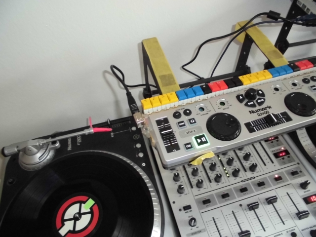
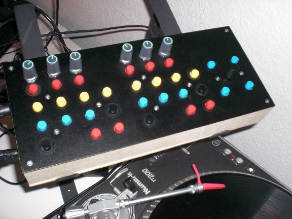
My current MIDI controller has a Mini-USB connector. This has to be one of the worst possible features of the device.  I was facing a lot of garbage data and MIDI dropouts recently and it all came down to faulty contacts caused by this connector.


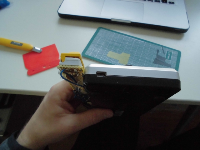
Even worse: the connector is attached on the left side of the device, drastically increasing the possibility of ripping it off unintentionally.


I already thought about attaching another type of USB connctor when I hacked the controller itself but somehow I forgot about it (or was too lazy or …).


Anyways… the problems I had were big enough  and I wanted to test this kind of hack for quite a long time so it’s finally enough to start thinking about it:


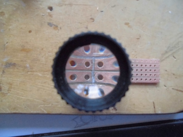
If you look very closely you see that there are 5 spring-loaded contacts inside a female Mini-USB connector. Right below every contact is a small hole. I guess that’s where the contact is stuffed into the plastic. My plan was to use these holes with a very thin wire so the wires would touch the contacts ‘from below’. In order to keep the wires from falling out I wanted to apply some pressure to the contacts via a thin piece of plastic.

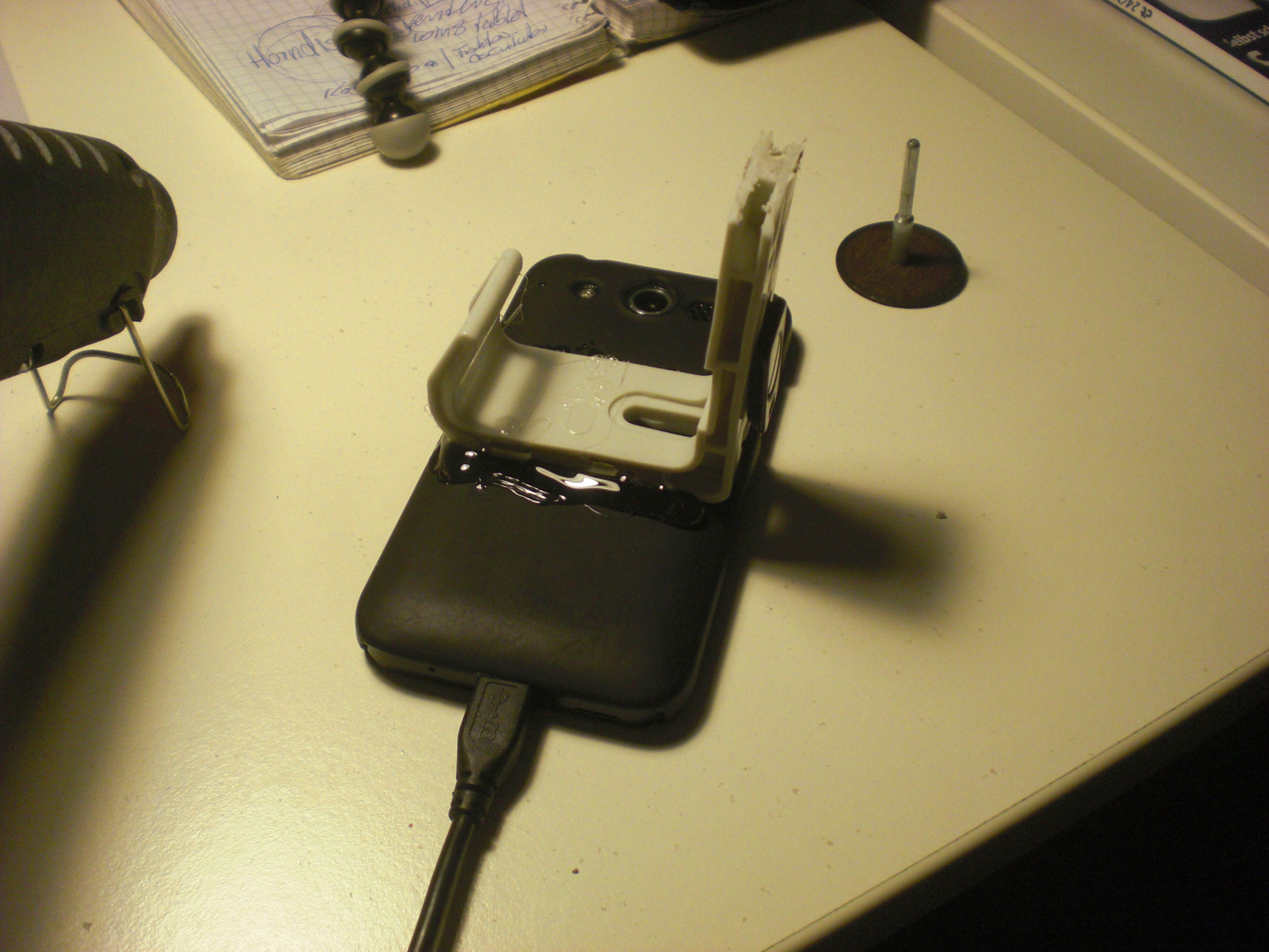
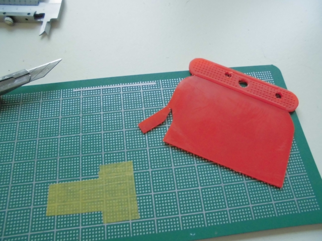
I had this one lying around and it turned out to have just the correct thickness. Only needed to cut a bit out of it.
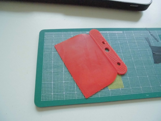
 

Excellent


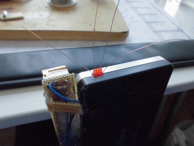
Here it all comes together (you only need 4 of the 5 contacts):


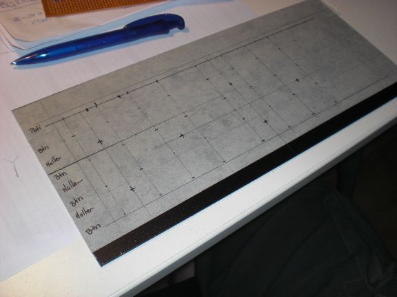
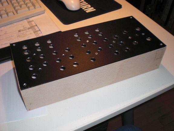
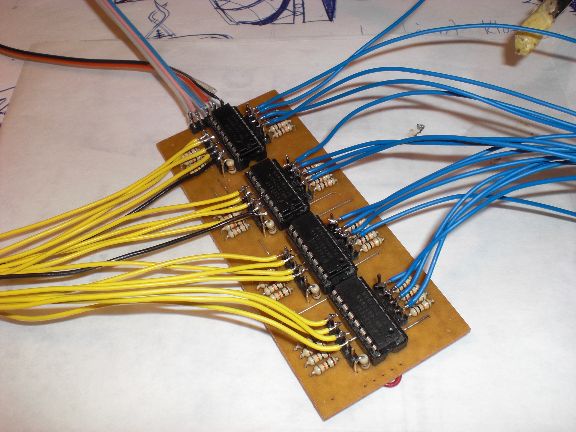
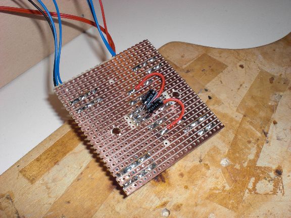
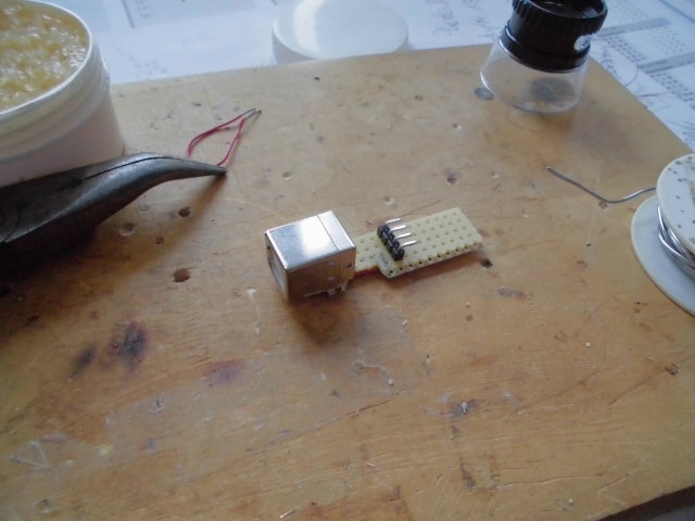
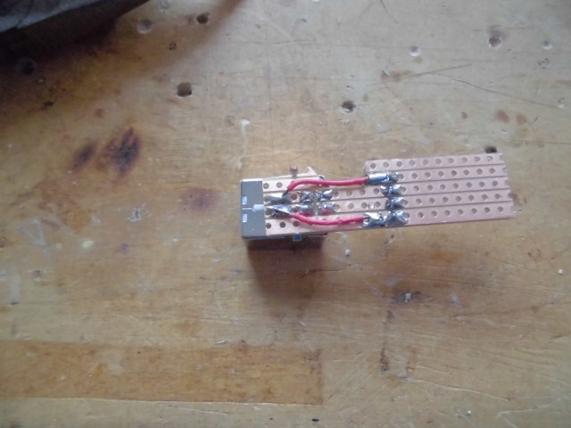
The wires are held in place surprisingly well so I built a small breakout-board with a somewhat sturdy USB B-Type connector:


Don’t forget to cut the coppertraces so the shield is not shortenend with any of the 4 pins. Of course I forgot that and only realized it after applying the first ton of hotglue …


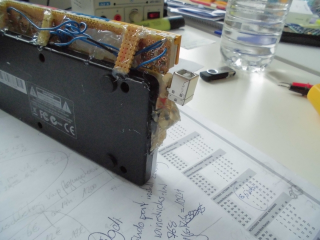
The board is attached to the side of the controller using hotglue, the wires are soldered to the corresponding pins. The wire itself is insulated by a clear coating which gets off as soon as you start soldering. As long as you don’t torture them too much there is no problem with shortcuts caused by touching wires.


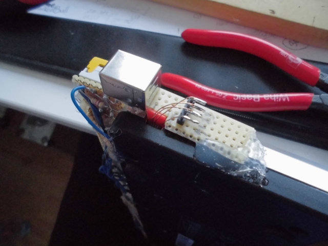
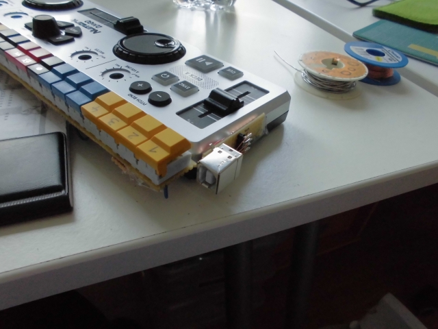
After i made sure everything is working fine I attached … slightly … more hotglue to make it ready for some rough handling:


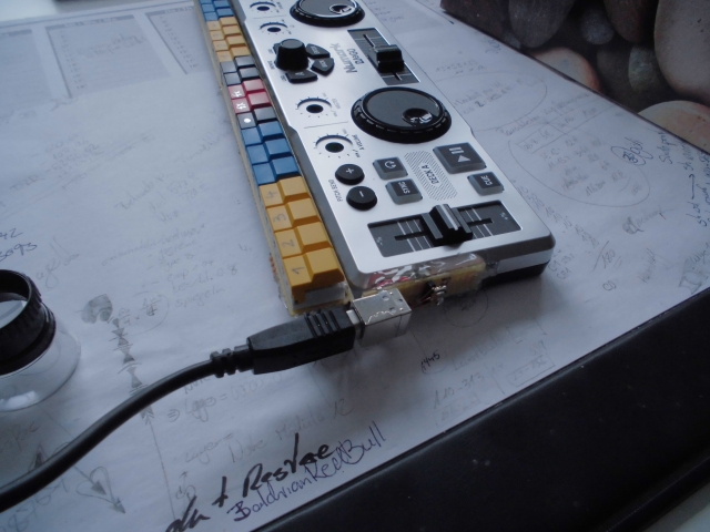
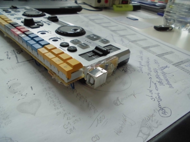
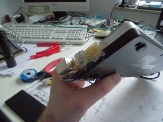
Looks fine, doesn’t it? I am not facing any faulty data or dropouts anymore, the connector is sturdy as hell and it is now pointing to/ from the back side of the device making it less prone to accidental pull-outs. Furthermore I now have to carry only one kind of USB cable with me whenever I’m out making music.

Torq Midi Controller

Quite some time ago I got myself the Torq System from M-Audio. Due to the fact that I don’t like the thought of controlling a musicsoftware via my computer’s mouse (just because it looks plain stupid in front of an audience) I used the BCR2000 from Behringer in conjuntion with Bome’s Midi-Translator for scrolling through the playlist, triggering fx, loading tracks, etc…


Good thing about it: it worked. Bad thing: Every now and then I am making music in a little bar and the dj ‘booth’ is quite packed. using the BCR2000 always meant using an extra laptop stand on top of the mixer so noone couls really see me.


That’s why I built my own Torq-dedicated MIDI-Controller.

Ladies and Gentlemen: I’m proudly presenting the Andy1000 Midi Controller Smile


This project is based on the Arduino platform with a “Duemilanove”-Board and an ‘168’ controller (pretty basic stuff).

Starting with a frontplate from a Server Rack. It was 19 inches wide but I cutted it down to 30cm (11.8 inches) to make it fit in front of my laptop. The marks for the holes have to be set rather precise since the buttons will later be fixed on a vectorboard.


After drilling. The housing is made of  plywood. This version is 6 cm high. I later built a new one which is only 4 cm.


That’s basically about what it will look like


The Buttons are attached to a DIN-module (Digital In)-board from uCapps.de that I had lying arround. Basically it’s just 4 shift registers. No real magic here.

Buttons mounted to a vectorboard


Interconnections. I didn’t really care about the pins I attached the buttons to since this will later be handled within the microcontroller’s code.


One extra rotary encoder (ALPS, 24 steps) for scrolling through the playlist. The vectorboards with the buttons will be fixed to the frontplate via screws. The Arduino and the DIN-Module will later be hot-glued to the bottom of the case.


This extra circuit was attached -after- all the basic soldering was done. It turned out that it was necessary to do some debouncing of the rotary encoder’s output. It is based on this scheme and helps a little bit.


Nearly finished, Knobs for the poties are still missing. I still (have to) use Bome’s Midi-Translator, especially for the ‘navigation’-controls (scroll up, down, etc) but who cares…


There we go!


And that’s another brilliant shot of how it looks like in real life…erm…well….the bar was already packed and I didn’t want to flashlight the crowd…

The code for the Arduino will be put up soon. It is still a bit crappy and needs some finetuning. Just contact me via the web form if you want to get it sooner.